Defogging and defrosting device for protective lens of a camera

a technology of protective lens and defrosting device, which is applied in the direction of camera filters, mountings, instruments, etc., can solve the problems of significant affecting the clarity of images, loss of lucidity of protective lens, blurred images captured by the camera

Inactive Publication Date: 2012-07-05
TOPVIEW OPTRONICS CORP
View PDF4 Cites 110 Cited by
  • Summary
  • Abstract
  • Description
  • Claims
  • Application Information

AI Technical Summary

Benefits of technology

[0011]The present invention is to solve the problem of loss of lucidity due to the humidity on the protective lens of cameras.

Problems solved by technology

However the lucidity of the transparent protective lens installed in front of the camera affects significantly the clarity of the image.
These factors will make the protective lens lose its lucidity and also make the images captured by the camera blurred.
However, the monitor cameras nowadays use mostly LED as the light-emitting device that generates little heat and can hardly heat the air inside the camera to the temperature enough to eliminate the humidity on the protective lens.
Furthermore, the transmission and convection of hot air are hard to control effectively to take effect on the protective lens and restore the lucidity of the humid protective lens.
Also, in order to save power and extent the life of the light-emitting devices, the light-emitting devices are usually set to be in function only in the night and the problem of frost and fog on the protective lens can thus not be solved timely and effectively.
The heater generates heat quickly on the central part of the protective lens which results in a rapid increase of temperature in the central area.
The large thermal difference between the central and outer areas of the protective lens would probably result in fractures due to thermal expansion.
The heater, exposed to the air, would get oxidized easily and thus reduce its life.
Also, attaching directly on the protective lens, the heater will fog the plastic protective lens due to local heating.
When proceeding camera lens adjustment or focus control which requires the removal of protective lens, the heater interferes and limits the removal of the protective lens and hinders the replacement of protective lens of the camera.
However, the high cost of conductive film and the special process needed to be apply on the protective lens don't correspond to the manufacture cost of the camera.
And again, when proceeding camera lens' adjustment or focus control which requires the removal of protective lens, the heater interferes and limits the removal of the protective lens and hinders the replacement of protective lens of the camera.

Method used


Image

  • Defogging and defrosting device for protective lens of a camera
  • Defogging and defrosting device for protective lens of a camera
  • Defogging and defrosting device for protective lens of a camera

Examples


first embodiment

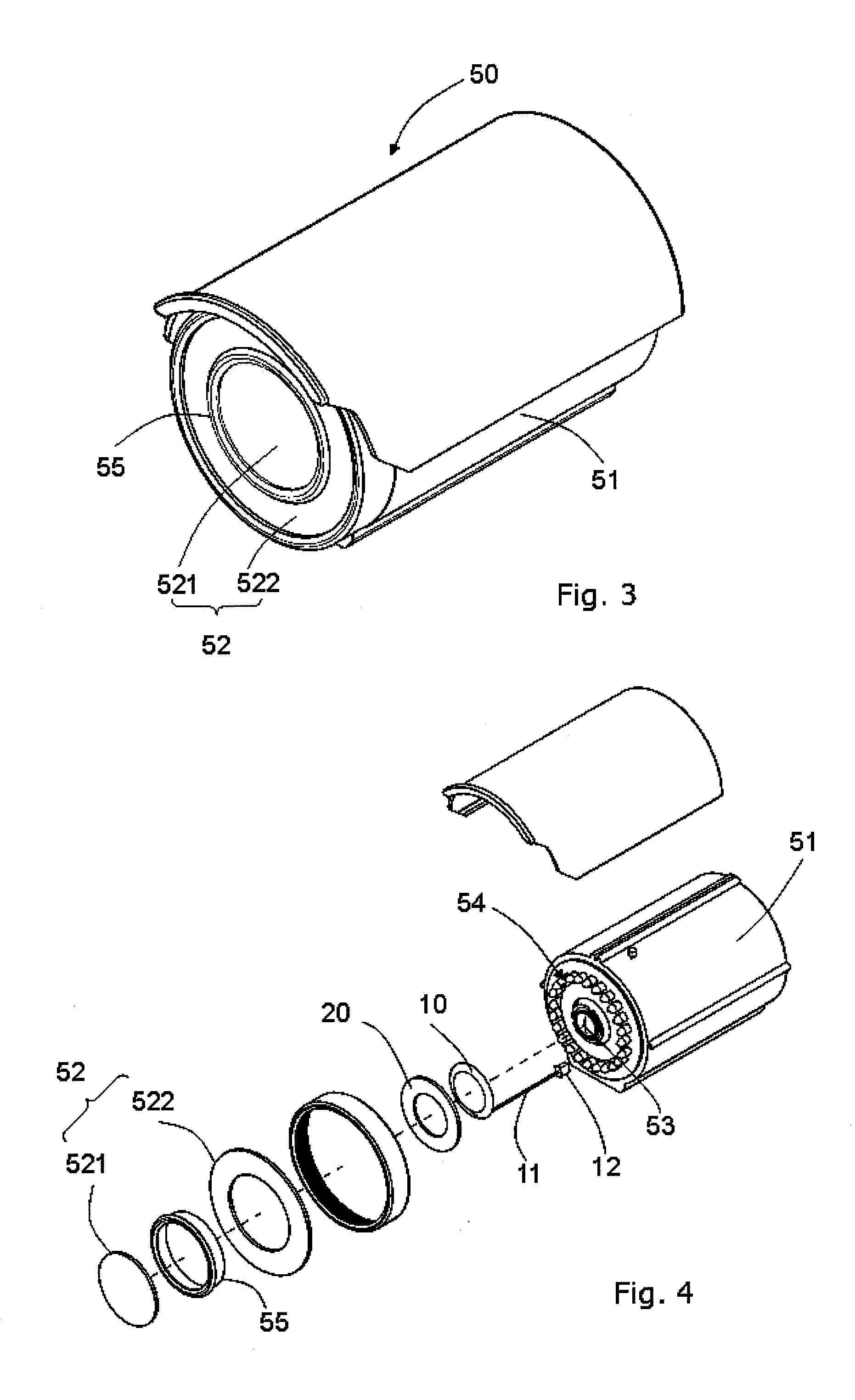
[0022]In FIG. 3 to FIG. 6, the present invention of defogging and defrosting device (1) is used on a bullet camera (50). The external structure of the bullet camera (50) includes a protective shell (51) and a planar protective lens (52) assembled to the front of the protective shell (51). The lens (53) of the camera and the light module (54) is mounted inside the protective shell (51). The light module (54) includes a control circuit panel (54) and a LED light (542) coupled to the control circuit panel (541).

[0023]In this embodiment, the protective lens (52) is planar and the heater (10) and thermal gasket (20) are flat annular. The heater (10) is set on the control circuit panel (541) and the thermal gasket (20) is contacting with the heater (10). A heat transfer element (55) is contacting with the thermal gasket (20) with its bottom and with the protective lens (52) with its top. In the drawings, the protective lens (52) are mounted with 2 concentric mirrors or glass (521, 522) an...

second embodiment

[0024]As shown in FIG. 7 to FIG. 10, the present invention, the defogging and defrosting device (1) is used on a dome camera (40). The external structure of the dome camera (40) includes a protective shell (41) and a semi-spherical protective lens (42) mounted at front of the protective shell (41). The lens (43) and light module (44) of the camera (40) are mounted inside the protective shell (41). The light module (44) includes a control circuit panel (44) and a LED light (442) coupled to the control circuit panel (441). A supporting element (45) is mounted with its bottom on the control circuit panel (441) of the light module (44). The defogging and defrosting device (1) is fixed on the supportive element (45). In this embodiment, the protective lens (42) is semi-spherical and the heater (10) and thermal gasket (20) are annular with the torus declining from the center toward the circumference at a preset angle. Corresponding slot (451) in designed at the top of the supporting eleme...

third embodiment

[0025]As shown in FIG. 11 to FIG. 13, the present invention, the defogging and defrosting device (1) is used on a dome camera (60). The external structure of the dome camera (60) includes a protective shell (61) and a semi-spherical protective lens (62) mounted at front of the protective shell (61). The lens (63) and focus device (64) of the camera (60) are mounted on a holder (65) inside the protective shell (61). Several cylindrical components (661) surround the lens (63) and the focus device (64) in a concentric way and have their bottoms mounted on a fixing element (67). An annular bracket (662) is set on the top of cylindrical components (661). The heater (10) of the defogging and defrosting device (1) is mounted at the inner wall of the annular bracket (662) and the thermal gasket (20) is mounted at the locating slot (663) on the top of the annular bracket (662). The annular bracket (662) is an insulator with high thermal conductivity that allows the heat generated by the heat...


PUM


Abstract

The present invention relates to a defogging and defrosting devices for the protective lens of camera, which includes a heater that is coupled to a control circuit panel, a thermal gasket that is in contact contacting with the heater, receives the heat from the heater and transmits the heat to the glass or mirror object which contacts with in order to avoid and prevent the loss of lucidity of the glass or mirror object due to humidity. The defogging and defrosting device is installed on the body of the camera instead of on the protective lens in order to avoid shading the camera view and to facilitate the removal of protective lens while adjusting the focus of the camera. It also facilitates the replacement of the protective lens of the camera.

Description

BACKGROUND[0001]1. Field of the Invention[0002]The present invention relates to a defogging and defrosting technology for glass object or mirror object using electric heating. To be more precise, it relates to a defogging and defrosting device for cameras.[0003]2. Description of the Related Art[0004]Image clarity is ultimately one of the main elements to evaluate the performance of photographic equipments or monitor devices. Improving the optical components can effectively increase the image clarity. However the lucidity of the transparent protective lens installed in front of the camera affects significantly the clarity of the image. This transparent protective lens is installed in front of the protective shell of the camera and has an adequate distance from the camera lens. The factors that affect the lucidity of the transparent protective lens include mist, vapor and frost. These factors will make the protective lens lose its lucidity and also make the images captured by the came...

Claims


Application Information

Patent Timeline
Patent Type & Authority Applications(United States)
IPC IPC(8): G03B17/00
CPCG03B17/55G03B11/048G03B11/00G02B27/0006
Inventor CHU, YI-CHIHHUNG, CHING-CHUNG
Owner TOPVIEW OPTRONICS CORP
Why Eureka
Try Eureka