

Automated torch
a torch and automatic technology, applied in the field of torch, can solve the problems of not being manufactured to withstand weather elements, deposited black soot on the outside of the head of the torch, and sending harmful pollutants into the atmospher
- Summary
- Abstract
- Description
- Claims
- Application Information
AI Technical Summary
Benefits of technology
Problems solved by technology
Method used
Image

Examples
Embodiment Construction
[0030]Referring now to the drawings, preferred illustrative embodiments of the present invention are shown in detail. Although the drawings represent embodiments of the present invention, the drawings are not necessarily to scale and certain features may be exaggerated to better illustrate and explain the present invention. Further, the embodiments set forth herein are not intended to be exhaustive or otherwise to limit or restrict the invention to the precise forms and configurations shown in the drawings and disclosed in the following detailed description.
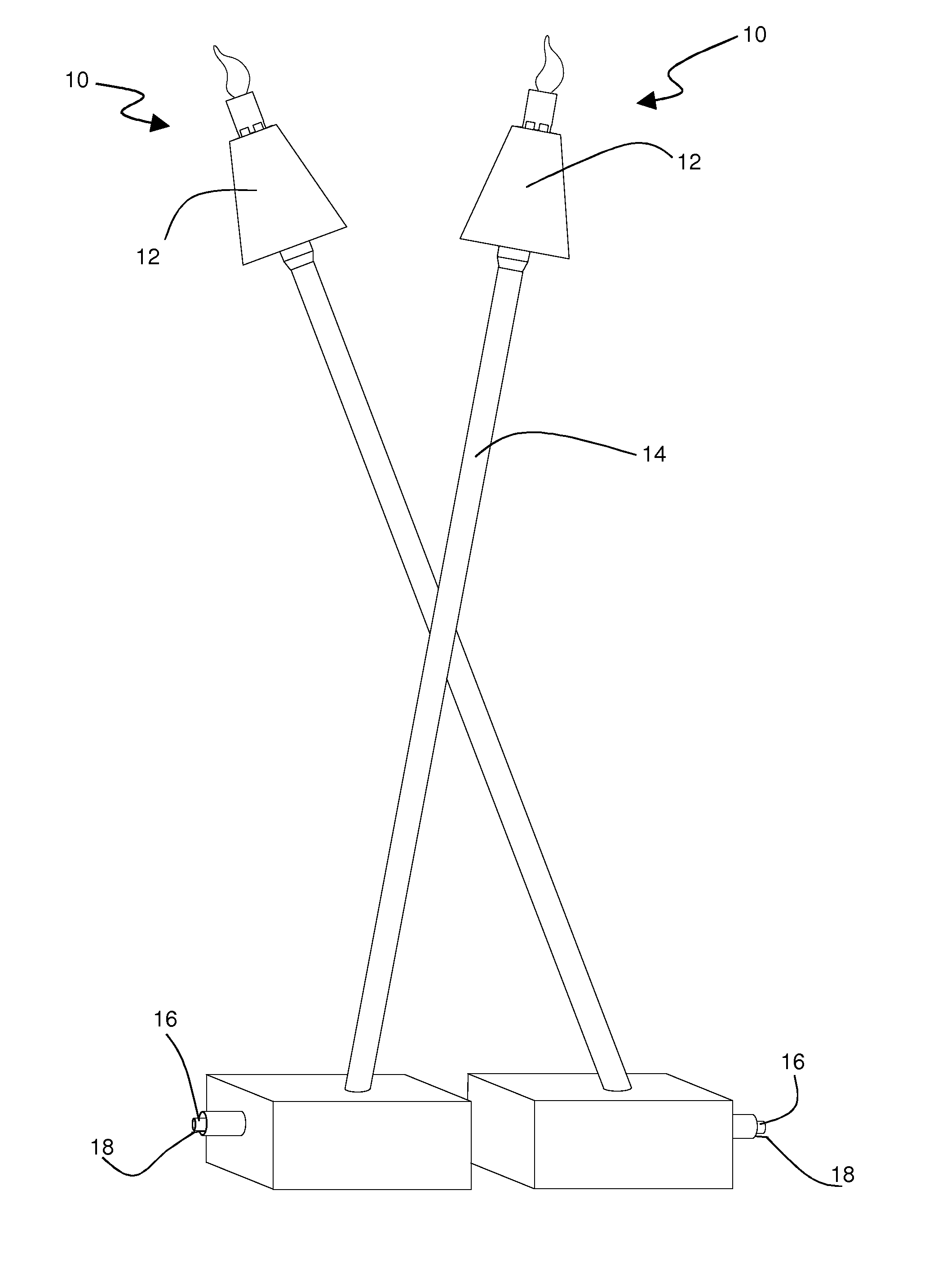
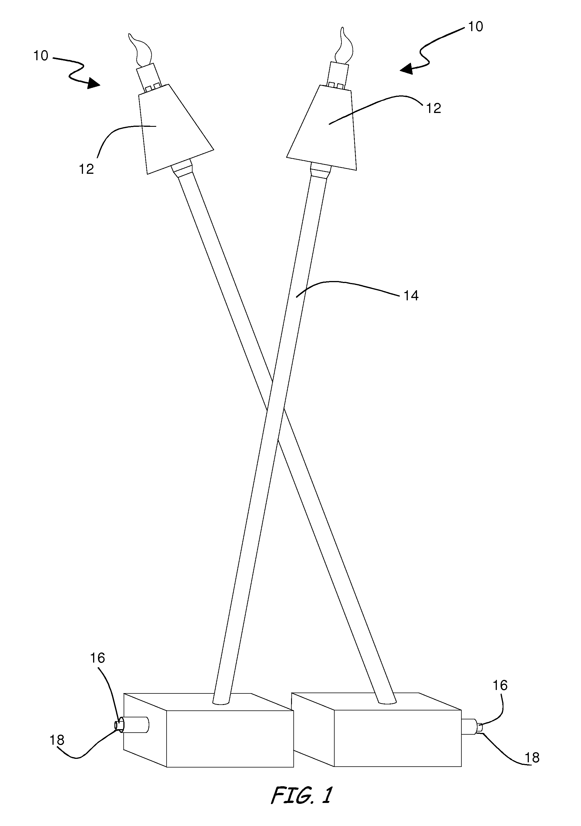
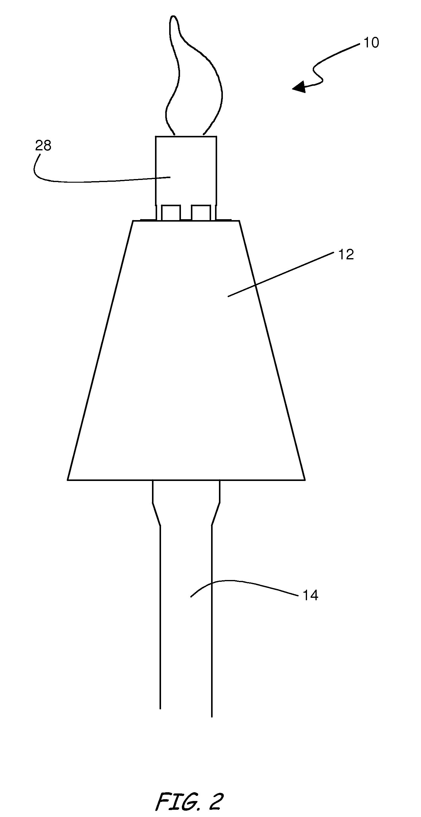
[0031]Now referring to the drawings, an automated torch 10 is illustrated in FIGS. 1-5. According to an embodiment of the present invention, torch 10 includes a head 12 and a pole 14. Head 12 will contain many of the features that will control the operation of torch 10. These features will be more fully described below. Pole 14 contains still further features for the operation of torch 10 as well as providing a rigid structure to...
PUM
 Abstract
Description
Claims
Application Information