Pumping device for vehicle seat cushion

a technology for vehicle seats and adjusting devices, which is applied in the direction of movable seats, transportation and packaging, etc., can solve the problems of excessive external force applied to the pinion gear, the occupant's inconvenience, and the inability to achieve the desired operational efficiency of the conventional seat height adjustment device,

Active Publication Date: 2012-11-01
DAEWON PRECISION IND
View PDF2 Cites 20 Cited by
  • Summary
  • Abstract
  • Description
  • Claims
  • Application Information

AI Technical Summary

Problems solved by technology

However, the conventional seat height adjusting device 1 produces the braking force using only the frictional force that is generated between the brake spring 40 and the brake drum 50 so that when an excessive external force is applied to the pinion gear 10 and a frictional force is generated between the brake spring 40 and the brake drum 50, the brake spring 40 may move inside the brake drum 50 due to the excessive external force and may not firmly fix the location of the seat cushion, the height of which has been adjusted.
This causes an occupant to frequently manipulate the actuating lever so as to repeatedly adjust the height of the seat cushion, thereby causing the occupant inconvenience.
Further, the excessive external force that is applied to the pinion gear 10 may easily deform or break the brake spring 40.
The deformed or broken brake spring 40 may fail to maintain a desired and constant clearance between the brake drum 50 and the brake spring 40 so that the conventional seat height adjusting device may not realiz...

Method used


Image

  • Pumping device for vehicle seat cushion
  • Pumping device for vehicle seat cushion
  • Pumping device for vehicle seat cushion

Examples


Embodiment Construction

[0036]Hereinbelow, a preferred embodiment of the present invention will be described in detail with reference to the accompanying drawings.

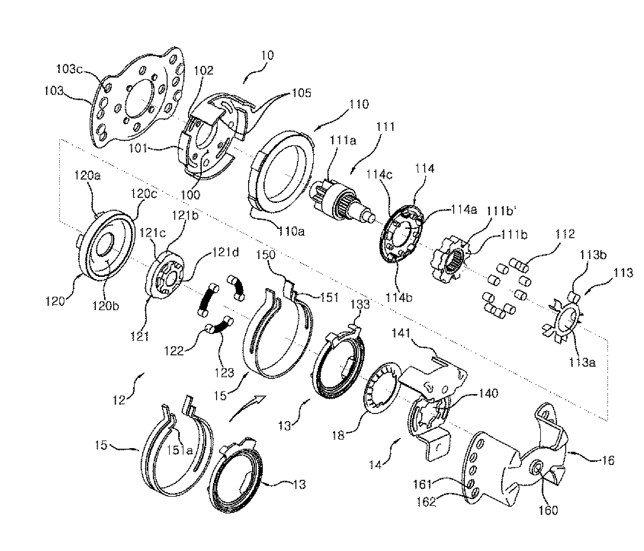
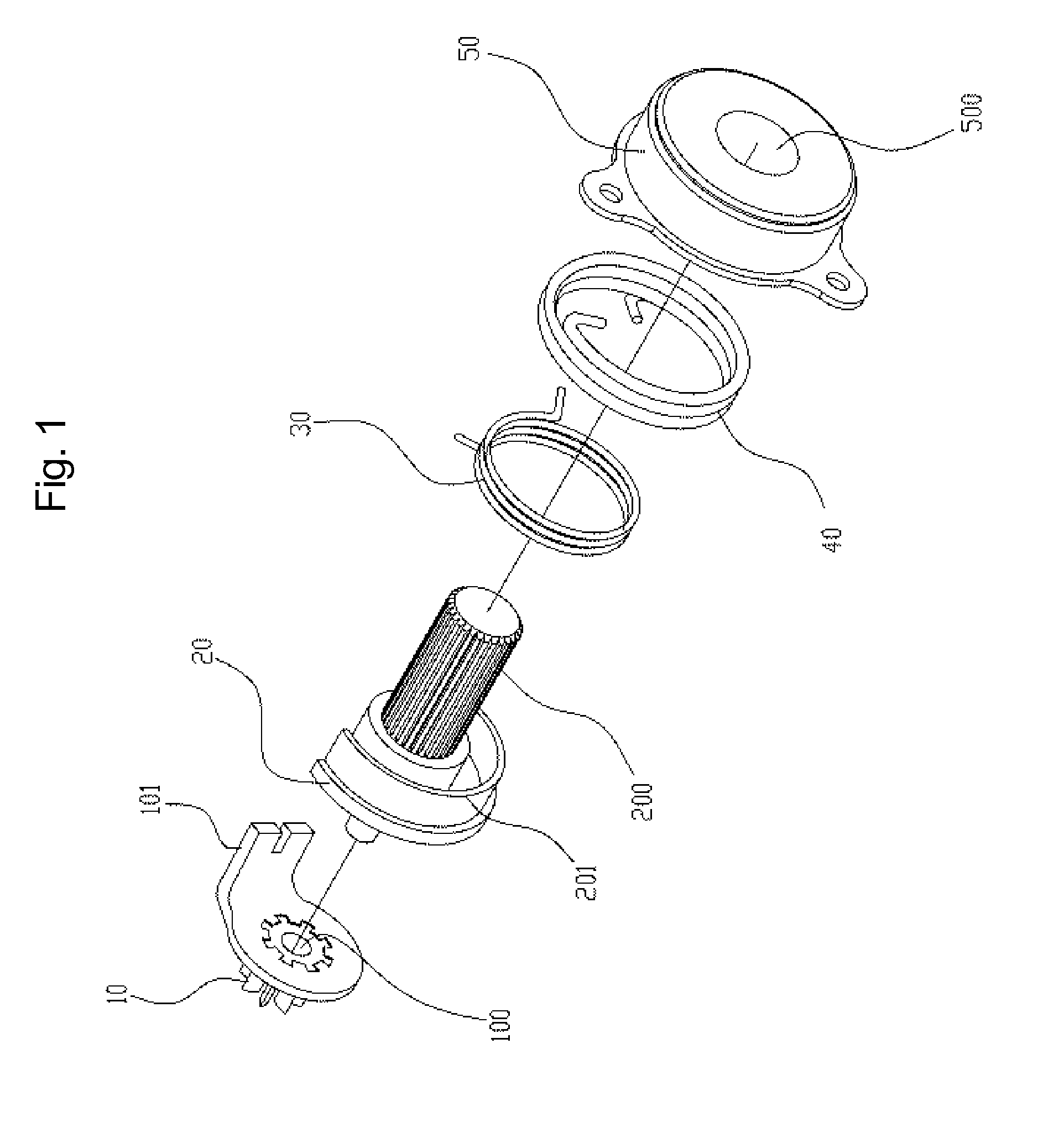
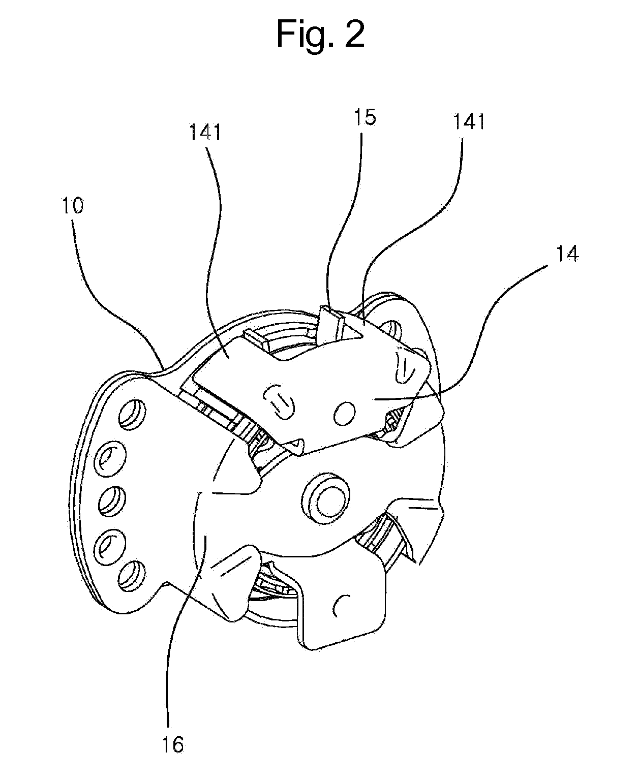
[0037]FIG. 2 is a perspective view of a pumping device for vehicle seat cushions according to the present invention, FIG. 3 is an exploded perspective view of FIG. 2 and FIG. 4 is another perspective view of the pumping device for vehicle seat cushions according to the present invention. FIG. 5 is an exploded perspective view of FIG. 4, FIGS. 6 through 9 are views illustrating the operation of a clutch unit and FIGS. 10 through 13 are views illustrating the operation of a brake unit.

[0038]As shown in FIGS. 2 through 13, the pumping device for vehicle seat cushions according to the present invention includes an inner cover 10, a brake unit 11, a clutch unit 12, a lever bracket 14, a return spring 15 and an outer cover 16.

[0039]In the pumping device for vehicle seat cushions having the above-mentioned construction according to the present invention...


PUM


Abstract

A pumping device for a vehicle seat cushion, which rotates a link gear mounted to the seat cushion as an actuating lever is rotated, thereby controlling the height of the seat cushion. This pumping device generates a uniform clutch force at the same position at all times and prevents undesired movement of the actuating lever so that the actuating lever can be located at the regular position at all times. In addition, when operating the actuating lever in the same direction continuously, the pumping device can minimize the degree of angle at which the actuating lever idles, so that the pumping device can improve the controllability of the actuating lever, thereby effectively transmitting the operating force of the actuating lever to the link gear. Therefore, this invention causes the user inconvenience and improves the quality of the vehicle seat, and remarkably improves assemblability and productivity of the pumping device.

Description

TECHNICAL FIELD[0001]The present invention relates, in general, to a pumping device for vehicle seat cushions and, more particularly, to a pumping device for vehicle seat cushions which is installed in a vehicle seat cushion and rotates a link gear of a vehicle seat cushion in response to a rotation of an actuating lever, thereby adjusting the height of the vehicle seat cushion.BACKGROUND ART[0002]Hereinbelow, the problems experienced in a conventional technique relating to the present invention will be described.[0003]Vehicle seats function to maintain sitting postures of vehicle passengers and are typically divided into separate seats, which are designed to allow one person to sit thereon and are installed in the front section of the passenger compartment of a vehicle, thereby forming a driver's seat and a front passenger seat, and bench-type seats or multi-row seats that are designed to allow several persons to sit thereon and are installed in the rear section of the passenger co...

Claims


Application Information

Patent Timeline
IPC IPC(8): F16D67/02B60N2/16
CPCB60N2/167B60N2/168F16H31/002F16D67/02F16B1/04B60N2/16B60N2/18
Inventor HUR, YOON-HOSIM, JAE-WON
Owner DAEWON PRECISION IND
Why Eureka
Try Eureka