Pumping device for vehicle seat cushion

a technology for vehicle seats and adjusting devices, which is applied in the direction of movable seats, transportation and packaging, etc., can solve the problems of excessive external force applied to the pinion gear, the occupant's inconvenience, and the inability to achieve the desired operational efficiency of the conventional seat height adjustment device,

Active Publication Date: 2014-09-02
DAEWON PRECISION IND
View PDF8 Cites 8 Cited by
  • Summary
  • Abstract
  • Description
  • Claims
  • Application Information

AI Technical Summary

Benefits of technology

[0016]Accordingly, the present invention has been made keeping in mind the above problems occurring in the related art, and is intended to provide a pumping device for vehicle seat cushions, which can always generate a constant clutching force at the same position and can prevent an actuating lever from being undesirably moved, and in which, when the actuating lever is continuously operated in the same direction, it is possible to minimize the degree of angle at which the actuating lever runs idle, so that the operating force of the actuating lever can be efficiently transmitted to a link gear and which can remarkably improve assemblability and productivity of the pumping device.Technical Solution
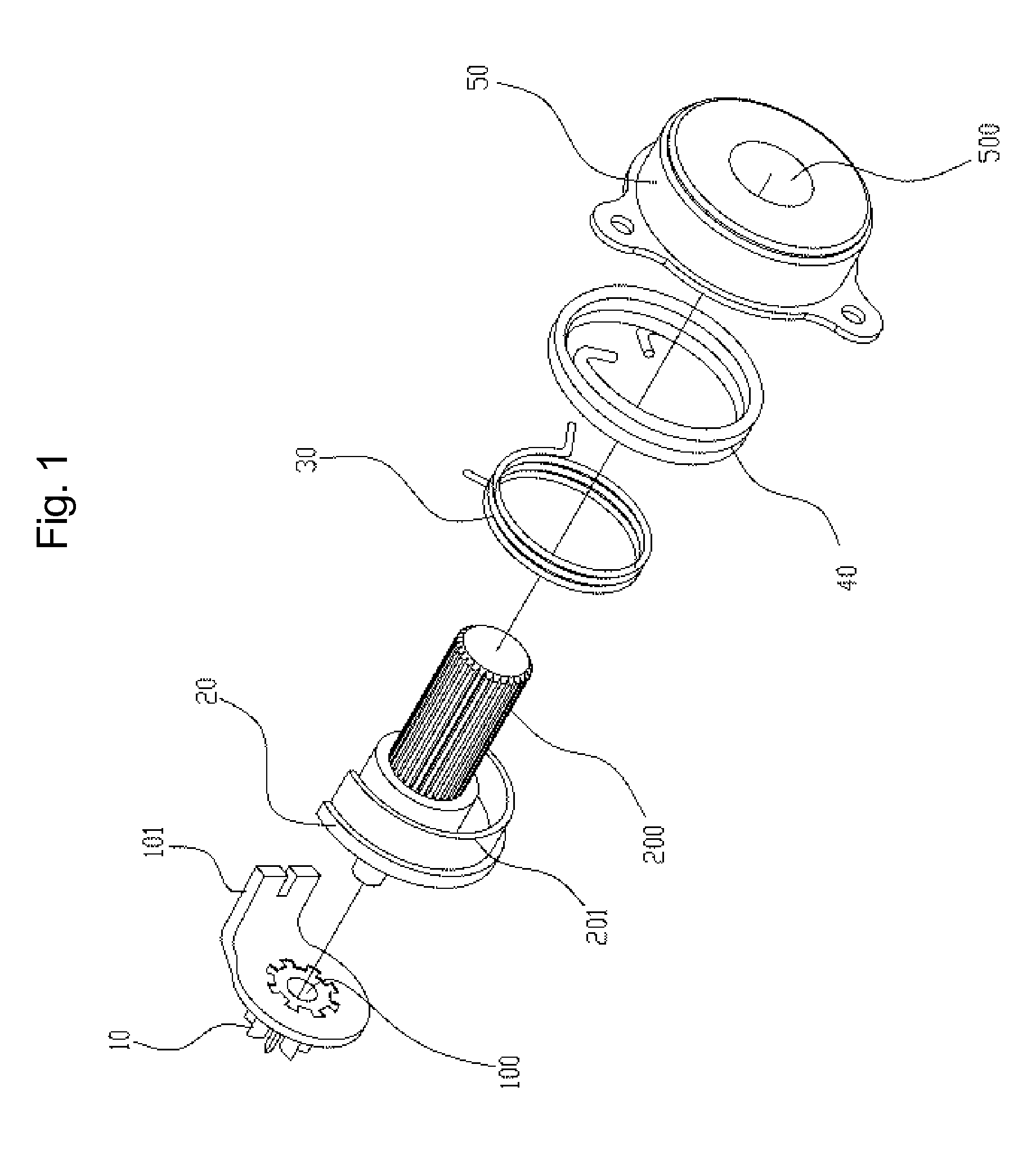
[0019]Further, each of the opposite ends of the return spring may be slit into two parts, in which first parts of the slit opposite ends of the return spring are bent and form respective lever bracket supports that hold the hooking pieces of the lever bracket and are held by the support jaws of the inner cover, and second parts of the slit opposite ends of the return spring are bent and form respective retainer supports that hold the hooking pieces of the retainer and are held by the support jaws of the inner cover, in which the retainer supports are shorter than the lever bracket supports so as to be free from interfering with the hooking pieces of the lever bracket.
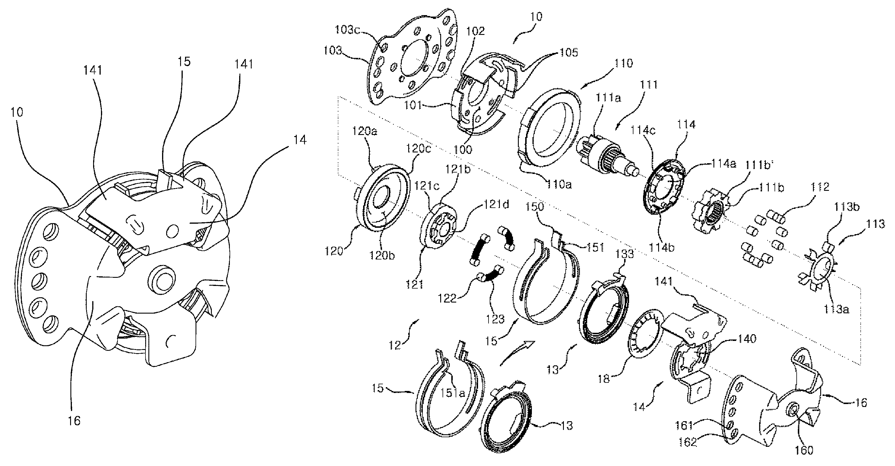
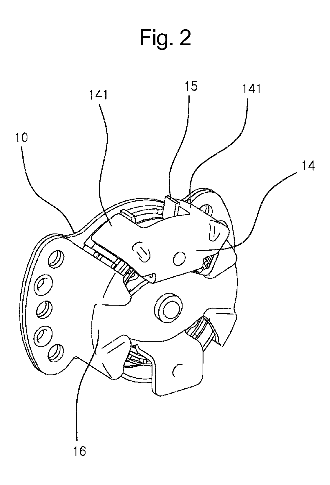
[0024]The pumping device for vehicle seat cushions according to the present invention is advantageous in that when the lever bracket is actuated to operate the pumping device, the two clutch rollers that are elastically biased by each clutch spring are operated in such a way that one clutch roller that is placed in the rotating direction of the lever bracket is supported by an associated rotating protrusion of the retainer and is retained in a stopped state until the other clutch roller that is placed in a direction opposed to the rotating direction of the lever bracket is jammed between the clutch bush and the clutch cam and generates a frictional force, so that a desired clutching force can always be generated at a predetermined position and the clutch rollers that are placed in the first sides of the clutch roller contact protrusions are brought into close contact with the power transmitting flat parts, thereby forming no gap between the clutch rollers and the power transmitting flat parts.
[0025]Further, even when the pumping device for vehicle seat cushions is not operated, the power transmitting protrusions of the clutch bush can always be retained in a state in which they are supported by the elastic hooks, so that no gap remains between the power transmitting protrusions of the clutch bush and the brake rollers. Further, when the actuating lever is actuated continuously, the power transmitting protrusions of the clutch bush are biased by the elastic hooks in a rotating direction of the actuating lever, so that the first side surfaces of the power transmitting protrusions of the clutch bush can be retained in a state in which they are brought into close contact with the brake rollers, thereby reducing the gap between the power transmitting protrusions of the clutch bush and the brake rollers by a space D that is defined between the first side surfaces of the power transmitting protrusions of the clutch bush and the brake rollers that are placed in the second sides of the elastic support pieces.
[0026]Therefore, the pumping device for vehicle seat cushions of this invention is advantageous in that the actuating lever is free from being undesirably moved and there is no part that is located in a freely movable position, so that it is possible to reduce the noise that may be generated by vibrations and to minimize the amount of rotating loss, thereby improving the operational efficiency of the pumping device and efficiently transmitting the rotating force of the actuating lever to the link gear, allowing a user to easily and efficiently manipulate the pumping device, and improving the quality of the vehicle seats.
[0027]Further, another advantage of the pumping device for vehicle seat cushions according to the present invention resides in that both the retainer and the lever bracket can be supported at the same time using one return spring, thereby improving the assemblability and productivity of the pumping device.

Problems solved by technology

However, the conventional seat height adjusting device 1 produces the braking force using only the frictional force that is generated between the brake spring 40 and the brake drum 50 so that when an excessive external force is applied to the pinion gear 10 and a frictional force is generated between the brake spring 40 and the brake drum 50, the brake spring 40 may move inside the brake drum 50 due to the excessive external force and may not firmly fix the location of the seat cushion, the height of which has been adjusted.
This causes an occupant to frequently manipulate the actuating lever so as to repeatedly adjust the height of the seat cushion, thereby causing the occupant inconvenience.
Further, the excessive external force that is applied to the pinion gear 10 may easily deform or break the brake spring 40.
The deformed or broken brake spring 40 may fail to maintain a desired and constant clearance between the brake drum 50 and the brake spring 40 so that the conventional seat height adjusting device may not realize the desired operational efficiency.
Further, when a user operates the conventional seat height adjusting device using the actuating lever, the operational rotating force is transmitted to the pinion gear 10 through the sub-spring 30 so that the efficiency of transmitting the rotating force is too low and this causes user inconvenience.
However, the conventional pumping device is problematic in that, when the user operates the pumping device so as to adjust the height of the seat cushion, an excessive amount of loss occurs in the operating amounts of both a brake unit and a clutch unit that are important parts of the pumping device, so that the effective upward or downward movement amount of the seat cushion is less than the manipulating amount of the user.
This prevents the manipulating force of the user that acts on the actuating lever from being efficiently transmitted to the link gear, thereby forcing the user to unnecessarily repeat the manipulation of the actuating lever and deteriorating the quality of the vehicle seats.

Method used


Image

  • Pumping device for vehicle seat cushion
  • Pumping device for vehicle seat cushion
  • Pumping device for vehicle seat cushion

Examples


Embodiment Construction

[0036]Hereinbelow, a preferred embodiment of the present invention will be described in detail with reference to the accompanying drawings.

[0037]FIG. 2 is a perspective view of a pumping device for vehicle seat cushions according to the present invention, FIG. 3 is an exploded perspective view of FIG. 2 and FIG. 4 is another perspective view of the pumping device for vehicle seat cushions according to the present invention. FIG. 5 is an exploded perspective view of FIG. 4, FIGS. 6 through 9 are views illustrating the operation of a clutch unit and FIGS. 10 through 13 are views illustrating the operation of a brake unit.

[0038]As shown in FIGS. 2 through 13, the pumping device for vehicle seat cushions according to the present invention includes an inner cover 10, a brake unit 11, a clutch unit 12, a lever bracket 14, a return spring 15 and an outer cover 16.

[0039]In the pumping device for vehicle seat cushions having the above-mentioned construction according to the present invention...


PUM


Abstract

A pumping device for a vehicle seat cushion, which rotates a link gear mounted to the seat cushion as an actuating lever is rotated, thereby controlling the height of the seat cushion. This pumping device generates a uniform clutch force at the same position at all times and prevents undesired movement of the actuating lever so that the actuating lever can be located at the regular position at all times. In addition, when operating the actuating lever in the same direction continuously, the pumping device can minimize the degree of angle at which the actuating lever idles, so that the pumping device can improve the controllability of the actuating lever, thereby effectively transmitting the operating force of the actuating lever to the link gear. Therefore, this invention causes the user inconvenience and improves the quality of the vehicle seat, and remarkably improves assemblability and productivity of the pumping device.

Description

TECHNICAL FIELD[0001]The present invention relates, in general, to a pumping device for vehicle seat cushions and, more particularly, to a pumping device for vehicle seat cushions which is installed in a vehicle seat cushion and rotates a link gear of a vehicle seat cushion in response to a rotation of an actuating lever, thereby adjusting the height of the vehicle seat cushion.BACKGROUND ART[0002]Hereinbelow, the problems experienced in a conventional technique relating to the present invention will be described.[0003]Vehicle seats function to maintain sitting postures of vehicle passengers and are typically divided into separate seats, which are designed to allow one person to sit thereon and are installed in the front section of the passenger compartment of a vehicle, thereby forming a driver's seat and a front passenger seat, and bench-type seats or multi-row seats that are designed to allow several persons to sit thereon and are installed in the rear section of the passenger co...

Claims


Application Information

Patent Timeline
Patent Type & Authority Patents(United States)
IPC IPC(8): F16D67/02B60N2/16F16B1/04F16H31/00
CPCB60N2/167F16D67/02B60N2/168F16B1/04F16H31/002B60N2/16B60N2/18
Inventor HUR, YOON-HOSIM, JAE-WON
Owner DAEWON PRECISION IND
Why Eureka
Try Eureka