Variable geometry guide vane for a gas turbine engine

a gas turbine engine and guide vane technology, which is applied in the direction of liquid fuel engine components, wind motors with parallel air flow, perpendicular air flow, etc., can solve the problems of increasing the weight of the strut, reducing the efficiency of the strut, and reducing the mechanical strength of the strut, so as to improve the performance of the strut and minimize the mass required, the effect of optimizing load balancing

Inactive Publication Date: 2009-12-15
RAYTHEON TECH CORP
View PDF12 Cites 182 Cited by
  • Summary
  • Abstract
  • Description
  • Claims
  • Application Information

AI Technical Summary

Benefits of technology

[0011]The present invention comprises a variable geometry inlet guide vane which provides the necessary working gas flow alignment while accommodating the extreme mechanical loading from a mid-turbine bearing frame in a light weight and compact assembly.
[0012]The guide vane of the present invention includes an internal mechanical load carrying spar which effectively transmits bearing loads through the hot gas path to an engine mount, spaced internally from a lightweight variable geometry, aerodynamic shell which provides the necessary directional alignment of gas flow to an associated turbine or compressor throughout varying engine operating conditions (aerodynamic and vibrating loads). A gap between the spar and the shell may accommodate cooling airflow therethrough to cool the guide vane from the extreme heat loads present in gas flow when the guide vane is employed in conjunction with a turbine. The gap also accommodates an actuation mechanism which connects to the interior of the shell and when actuated, adjusts the aerodynamic shape of the shell. In the preferred embodiment the actuation mechanism comprises a cam-actuated, four bar linkage grounded to the spar and attached at, at least one output link thereof, to the interior of the shell. Movement of the output link adjusts the position of an associated portion of the aerodynamic shell, thereby adjusting the shape thereof to optimize load balancing between the pressure and suction surfaces thereof and to “tune” the shape of the shell to varying operating conditions of the engine to enhance the performance thereof.
[0013]To reinforce the spar and thereby minimize the mass required to accommodate thereof mechanical load, the spar is provided with stiffeners around its periphery to which the linkage may be grounded.

Problems solved by technology

While making such struts hollow to accommodate the flow of cooling air therethrough may suggest itself, hollowing out such struts will necessarily weaken them, thereby detracting from the struts' ability to carry the high mechanical loads placed thereon by the bearings.
Increasing the mass of the struts to handle such high mechanical bearing loads and accommodate the high thermal loading thereof as well, would necessarily severely increase the strut's weight and therefore be contrary, the goal of reducing the weight of the engine.
Since such guide vanes only accommodate aerodynamic loading (both steady state and transient) from the gases passing through the turbine and not the much higher mechanical loading from the bearings as do the struts described hereinabove, such guide vanes tend not to be as mechanically robust as the struts.
Using separate struts and inlet guide vanes imposes a significant restriction on the flow of working fluid from the high to the low-pressure turbine and adds significant weight to the engine.
Accordingly, a combined strut and low-pressure turbine inlet guide vane would be desirable but, heretofore, the diverse load (aerodynamic and mechanical) and temperature handling requirements of those two components have rendered the integration thereof into a single component difficulty if not impossible to achieve.

Method used


Image

  • Variable geometry guide vane for a gas turbine engine
  • Variable geometry guide vane for a gas turbine engine
  • Variable geometry guide vane for a gas turbine engine

Examples


Embodiment Construction

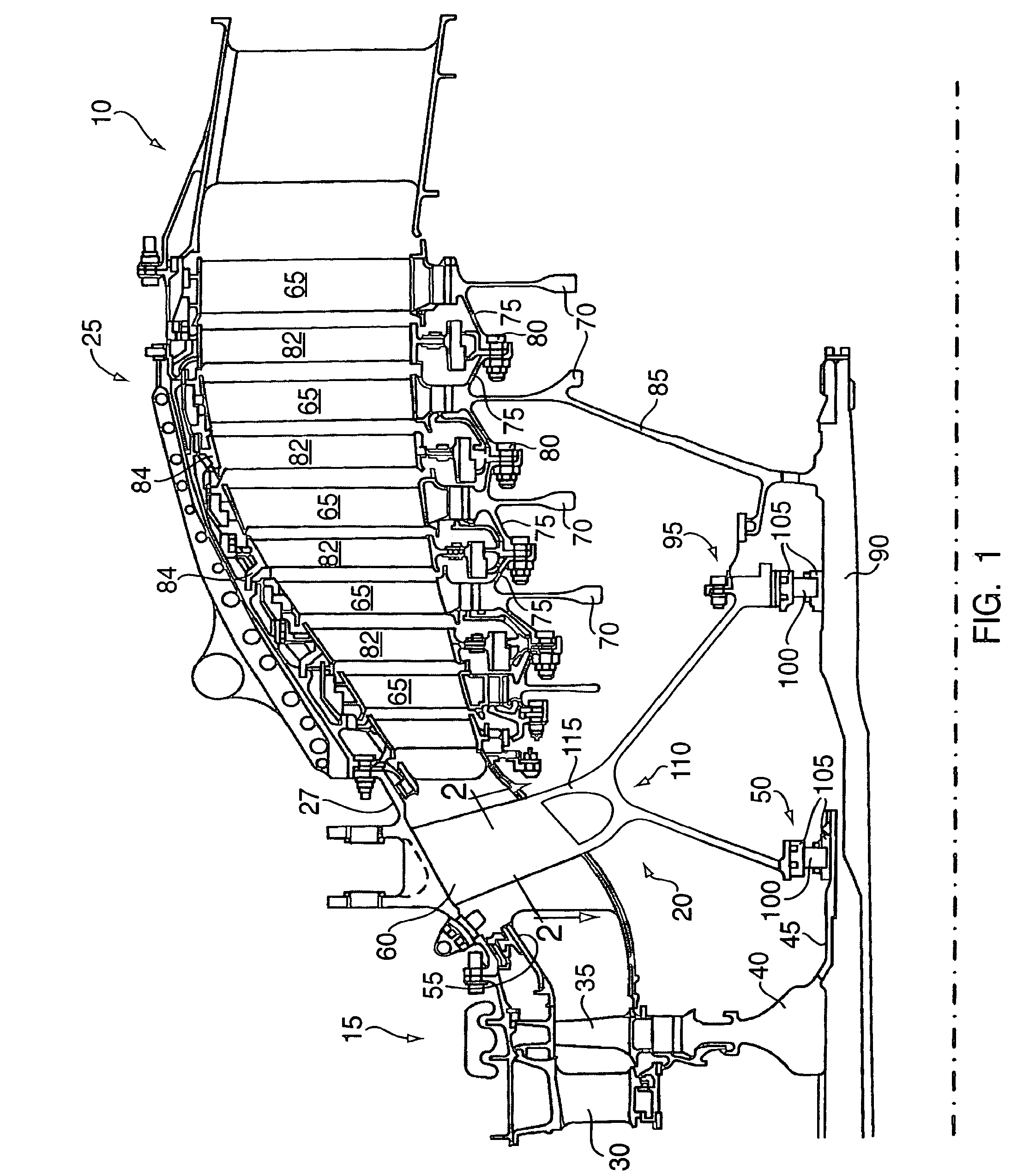
[0018]Referring to the drawings and particularly FIG. 1 thereof, the turbine section of a modern gas turbine aircraft engine is shown generally at 10. Turbine section 10 comprises a high-pressure turbine section 15, mid-turbine bearing frame 20 and low-pressure turbine section 25 all disposed within the engine's case 27.

[0019]High-pressure turbine 15 comprises an inlet guide vane 30 which properly aligns exhaust gases from the combustor (not shown) with the inlet of the high-pressure turbine. The high-pressure turbine itself comprises one or more rows of turbine blades 35 mounted on the rim of a disk 40 in a manner well known in the art. Disk 40 is attached in any known manner to hollow high-pressure shaft 45 supported at the end thereof by high pressure bearing assembly 50.

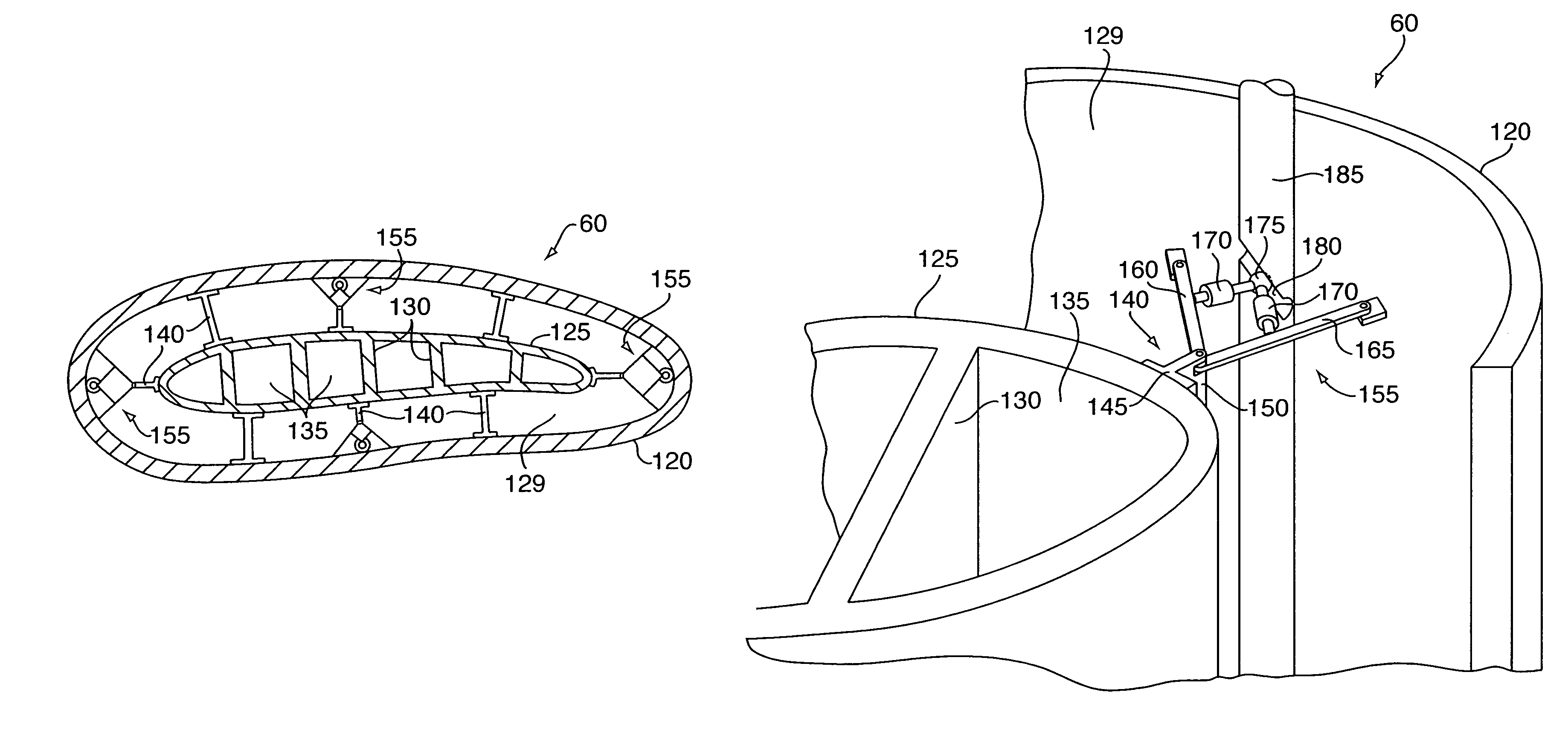
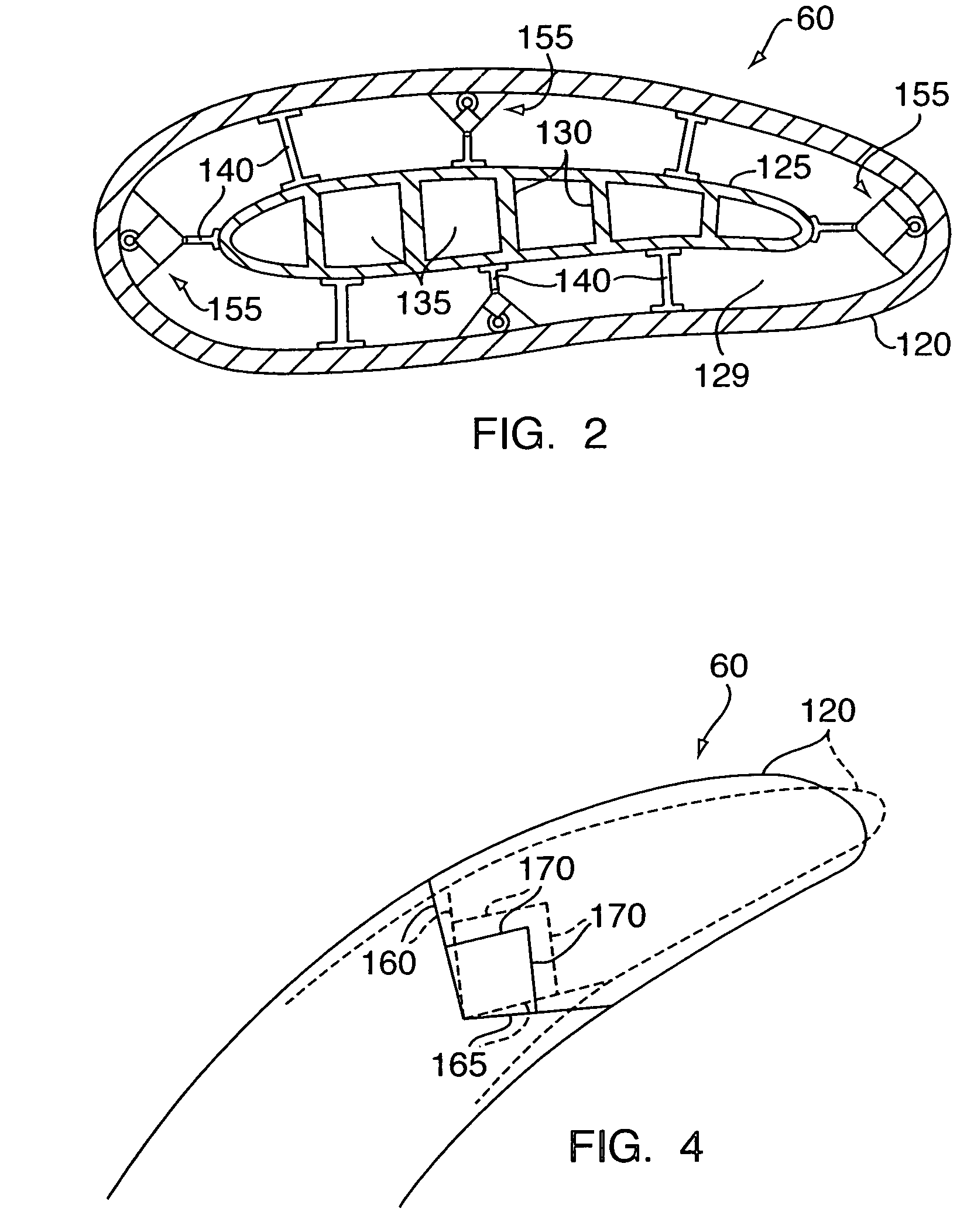
[0020]High-pressure turbine 15 exhausts into an annular flow channel 55 which accommodates the turbine inlet guide vane 60 of the present invention. Guide vane 60 turns the working fluid exhausted from high-press...


PUM


Abstract

A variable geometry inlet guide vane for a gas turbine aircraft engine includes an aerodynamic shell for turning inlet flow to a turbine or compressor and an internal spar spaced from the airfoil shell by an air gap. A number of actuation mechanisms grounded to the spar and connected to the inner surface of the aerodynamic shell adjust the shape of the shell in response to varying operating conditions of the engine, imbalanced aerodynamic loading of the shell or vibration or other transient loads on the shell.

Description

BACKGROUND OF THE INVENTION[0001]1. Technical Field[0002]This invention relates generally to aircraft gas turbine engines and particularly to a turbine inlet guide vane therefor.[0003]2. Background Art[0004]The operation of turbofan gas turbine engines is well known. Such engines include a serial arrangement of a fan, low and high-pressure compressors, a combustor, and high and low-pressure turbines. Air admitted into the inlet of the engine is compressed by the engine's compressor. The compressed air is then mixed with fuel in the engine's combustor and burned. The high-energy products of combustion of the burned air fuel mixture (often referred to a “hot gas” or “working fluid”) then enter the turbine which extracts energy from the mixture in order to drive the compressor and fan. That energy extracted by the turbine above and beyond that necessary to drive the compressor and fan, exits the engine at the core engine exhaust nozzle thereof, producing thrust which powers the associa...

Claims


Application Information

Patent Timeline
Patent Type & Authority Patents(United States)
IPC IPC(8): F04D29/44F04D29/54
CPCF01D5/148F01D9/041F01D9/065F01D17/162F01D25/162F04D27/0253F04D29/541F04D29/563F04D27/0246Y02T50/673F05B2240/311Y02T50/671Y02T50/60
Inventor SOMANATH, NAGENDRAKUMAR, KESHAVA B.
Owner RAYTHEON TECH CORP
Why Eureka
Try Eureka