Task allocation method for wireless sensor

A wireless sensor and task allocation technology, applied in wireless communication, advanced technology, network traffic/resource management, etc., can solve the problems that the algorithm cannot meet the application environment, the algorithm cannot jump in time, and weaken the optimization ability

Active Publication Date: 2018-03-20
BEIJING UNIV OF POSTS & TELECOMM
View PDF5 Cites 17 Cited by
  • Summary
  • Abstract
  • Description
  • Claims
  • Application Information

AI Technical Summary

Problems solved by technology

However, the patent uses a weighted summation method to model multiple objectives and converts it into a single-objective optimization model. When the algorithm is optimized, it may weaken the optimization ability of a certain objective according to the weighted value, resulting in the final optimization plan. Not optimal task assignment
[0006] Although the nodes in the wireless sensor network are statically deployed, when new tasks arrive, the current task allocation scheme may no longer be applicable
Most of the existing task allocation algorithms consider one task allocation, ignoring the continuous arrival of tasks, and in the optimization process of the intelligent optimization algorithm, if the environment changes, the algorithm cannot jump to the current environment state in time to optimize, resulting in the final The optimized algorithm cannot meet the actual application environment

Method used


Image

  • Task allocation method for wireless sensor
  • Task allocation method for wireless sensor
  • Task allocation method for wireless sensor

Examples


Embodiment Construction

[0051] The present invention will be described in detail below through the accompanying drawings and examples.

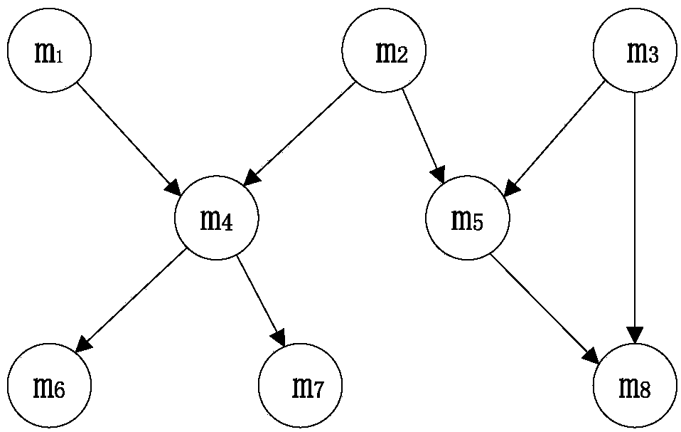
[0052] An embodiment is: assign 8 tasks to 30 sensor nodes.

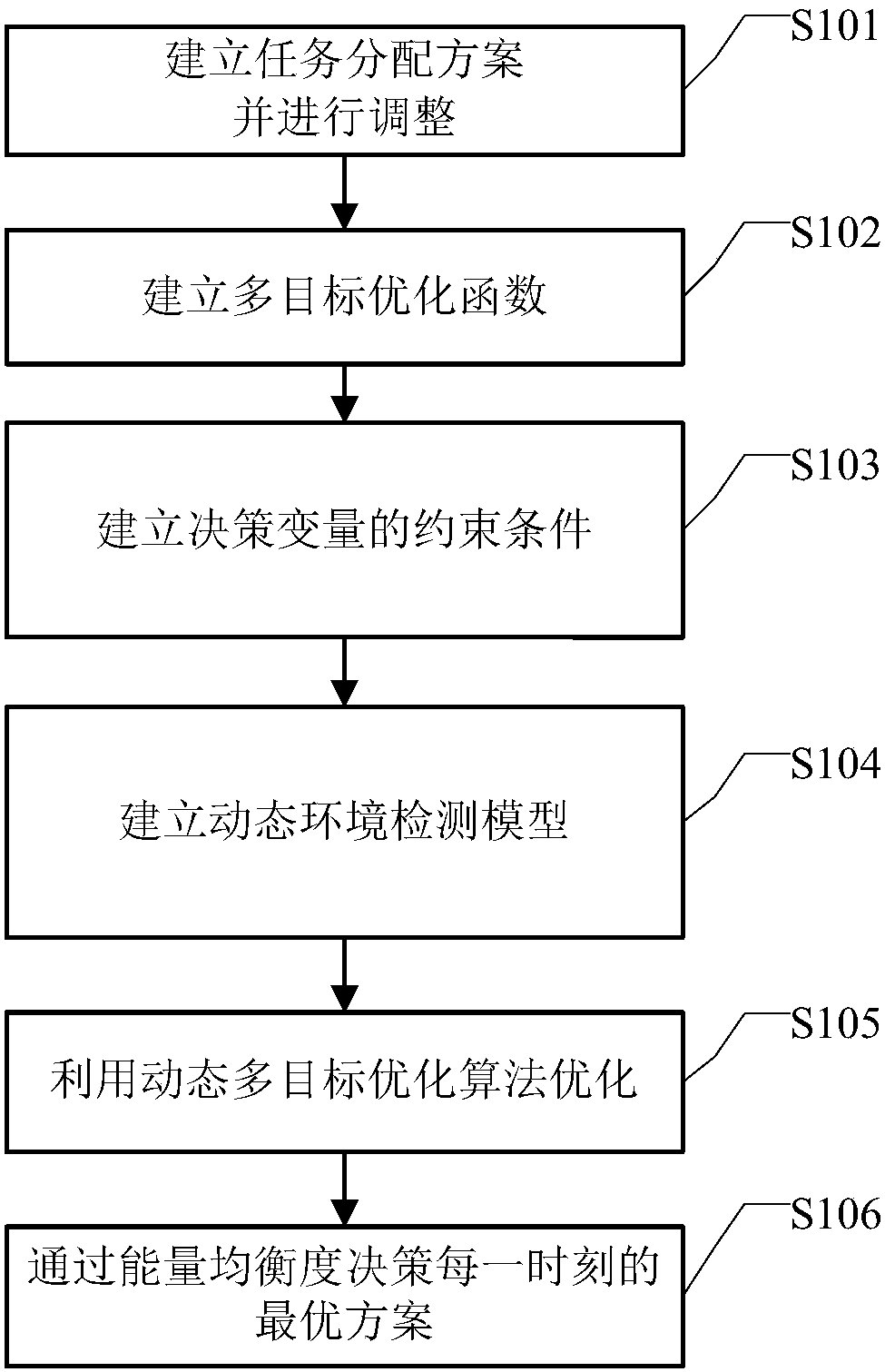
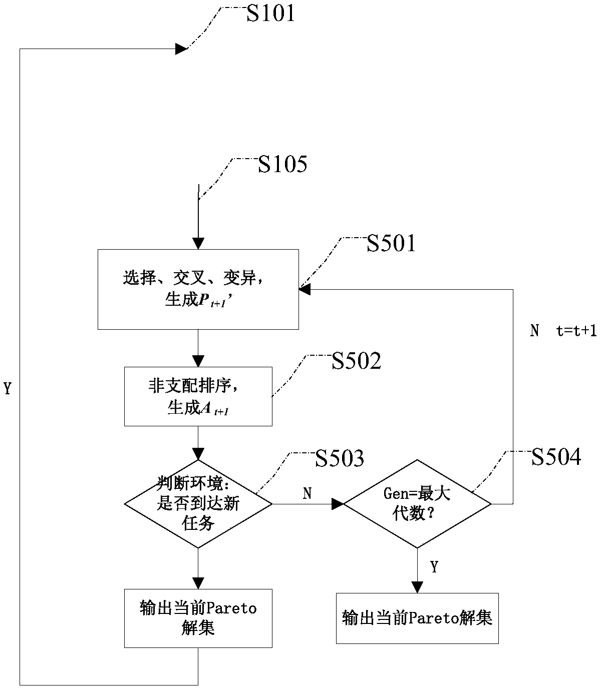
[0053] combine figure 1 and image 3 Illustrate the concrete flow process of the present invention scheme, this method comprises:

[0054] Step S101, initialize the task allocation scheme, randomly map the tasks to the wireless sensor nodes, adjust the initial task allocation scheme according to the task communication relationship between the DAG graphs, insert the current task with multiple successor tasks into the routing broadcast task, and Select the nearest node as the routing broadcast node, and make the remaining energy value less than a certain threshold e th The node mark of , will no longer assign tasks;

[0055] Specifically, select the initial population size pop, the maximum evolutionary algebra MaxIt and the parameters of the enhanced Pareto evolutionary algorithm, and initialize an empt...


PUM


Abstract

The invention discloses a task allocation method for a wireless sensor. The task allocation method for the wireless sensor comprises the following steps: establishing a task allocation model of a wireless sensor network, and adjusting the initial task allocation scheme according to the communication relationship between tasks; establishing a multi-objective optimization function combined with thetask load, the communication relationship, the node processing speed and the fault probability an so on; setting constraint conditions of the dynamic multi-objective optimization algorithm according to the number of the sensor nodes and the deadline of completing the task; establishing a dynamic environment detection model for judging whether a new task arrives or not; updating the task allocationscheme by means of the dynamic multi-objective optimization algorithm, and detecting the dynamic environment in real time to obtain the Pareto optimal solution set after every environment change; andselecting the solution with the most balanced energy consumption in the Pareto optimal solution set as the optimal task allocation scheme. According to the invention, the effectiveness indexes such as the energy consumption, the time and the reliability is optimized by means of the dynamic multi-objective task allocation method, so as to obtain the comprehensive optimal scheme with the shortest task completion time, minimum energy consumption and maximum reliability.

Description

technical field [0001] The invention relates to the field of wireless sensor network communication, in particular to a wireless sensor task assignment method. Background technique [0002] Wireless sensor networks have been widely used in military, disaster early warning, regional monitoring, smart home and other fields, which usually consist of a large number of sensors with relatively low computing power and limited energy supply. Once the wireless sensor is deployed, it will be in a static state, and there will be no human intervention and management for a long time. The sensor is easy to cause node failure, malfunction or death due to excessive energy consumption or failure, and change the topology of the wireless sensor network. Therefore, the basic challenge of the network is to achieve a certain energy efficiency while the application runs reliably, so as to extend the life cycle of the network. As the monitoring and data processing of sensor networks become more and...

Claims


Application Information

Patent Timeline
Patent Type & Authority Applications(China)
IPC IPC(8): H04W28/02H04W72/04H04W84/18
CPCH04W28/021H04W72/04H04W84/18Y02D30/70
Inventor 张洪光郭凤吴帆范文浩刘元安
Owner BEIJING UNIV OF POSTS & TELECOMM
Why Eureka
Try Eureka