Pressure control valve with aperture

Inactive Publication Date: 2012-11-29
SVM SCHULTZ VERW
View PDF25 Cites 1 Cited by
  • Summary
  • Abstract
  • Description
  • Claims
  • Application Information

AI Technical Summary

Benefits of technology

[0006]It is an object of the present invention to improve the state of the art such that, when the magnetic par

Problems solved by technology

The problem that existed here was that a metal-cutting machining of the often very filigree activation rods is only possible to a certain limit of the components, that means to a certa

Method used


Image

  • Pressure control valve with aperture
  • Pressure control valve with aperture
  • Pressure control valve with aperture

Examples


Embodiment Construction

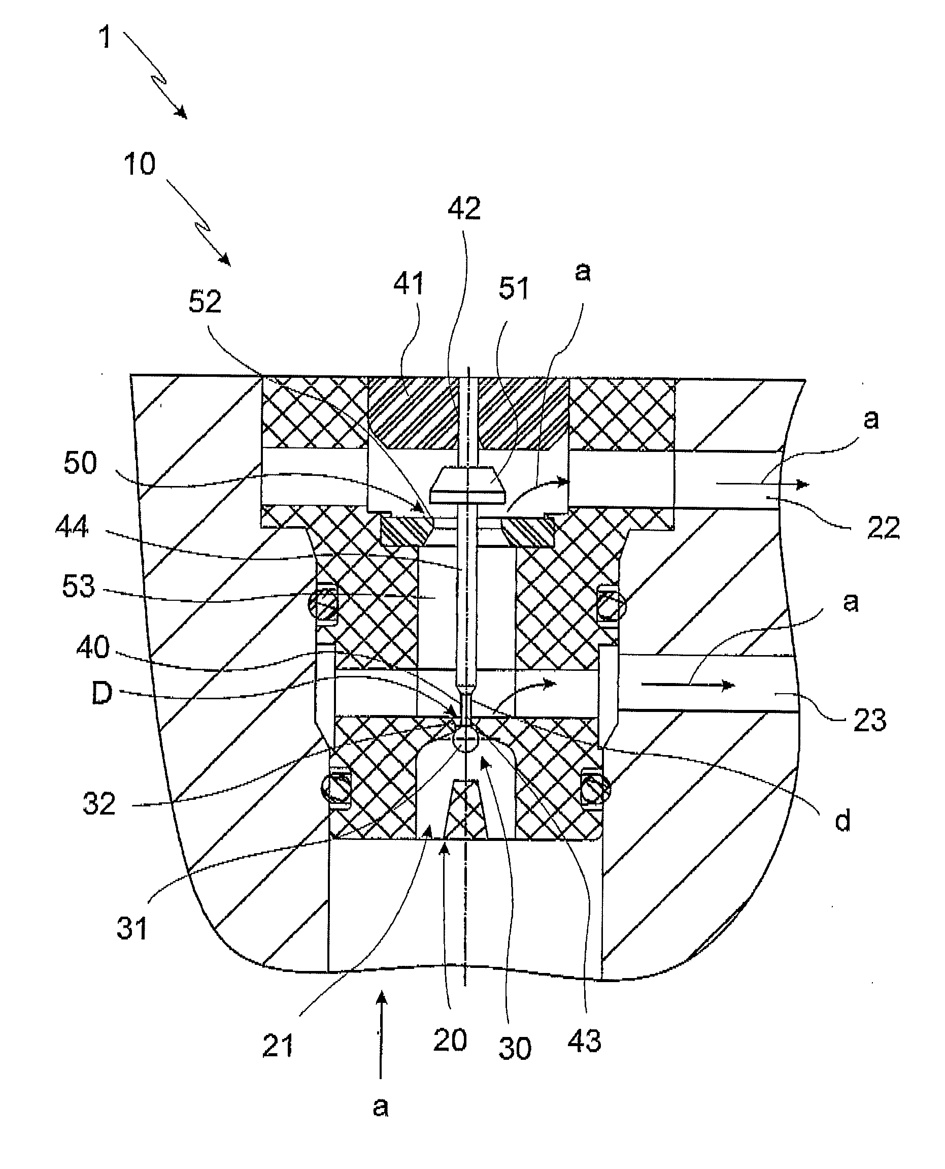
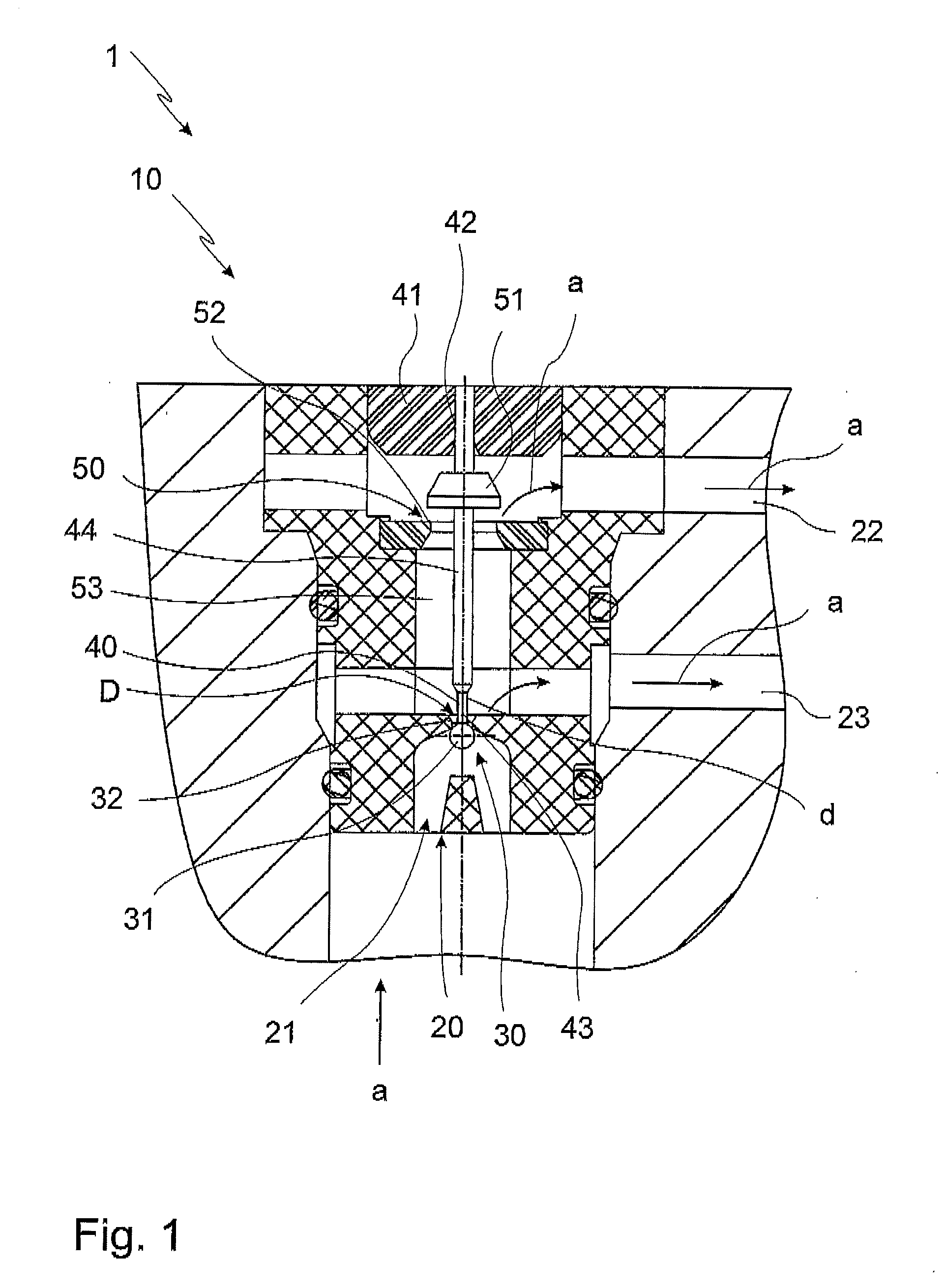
[0035]An electro-magnetic pressure control valve according to the invention is shown in FIG. 1 in a lateral sectional representation. The pressure control valve 1 consists here of a magnetic part 10 arranged in the drawing in the upper area. The magnetic part 10 comprises at least one electrically triggered coil, a coil core and a traversingly guided armature; the traversingly guided armature acts on the activation rod 40 penetrating the magnetic core 41 in a penetration bore hole 42.

[0036]Below the magnetic part 10, the valve part 20 is linked. The valve part 20 is formed, among others, by the feed 21 arranged in the view shown here on the underside, the return 22, and the consumer connection 23 provided here between the feed 21 and the return 22.

[0037]A plurality of arrows a indicates the flow direction of the pressurized medium that is controlled or regulated by the control pressure valve. The medium enters the control pressure valve 1 in the feed 21 under pressure, and leaves it...


PUM


Abstract

The invention refers to an electro-magnetic pressure control valve with a magnetic part and a valve part. The magnetic part has at least on coil that can be electrically triggered, a coil core and an armature guided traversingly. The valve part has a feed for the pressurized medium, a return and a consumer connection. The valve part has at least two seat valves that can be closed each by a valve element.

Description

BACKGROUND OF THE INVENTION[0001]The invention refers to an electro-magnetic pressure control valve with a magnetic part of at least one coil that can be electrically triggered, a coil core and an armature that is guided traversing and a valve part having a feed for the pressurized medium, a return and a consumer connection. The valve part has here at least two seat valves that each can be sealed by a valve element. The seat valves or the valve elements are in operative connection with the armature. At the seat valve first seen in direction of medium flow a loose valve element is provided.[0002]Electro-magnetic pressure control valves of this type are known, for example, from the European patent application EP 1 004 066.[0003]Control pressure valves of this type are employed, for example, in automatic transmissions in vehicles. These pressure control valves are constructed such that in direction of the medium flow in the feed a first seat valve is arranged separating the consumer co...

Claims


Application Information

Patent Timeline
IPC IPC(8): F16K31/12
CPCG05D16/2033
Inventor SCHERER, GEORGMANG, HELMUTSCHREIBER, FLORIAN
Owner SVM SCHULTZ VERW
Why Eureka
Try Eureka