Zoom lens

a zoom lens and zoom technology, applied in the field of zoom lenses, can solve the problems of difficult to achieve the miniaturization of the zoom lens, and the zoom lens described in the patent reference does not fully satisfy the demands of high performance and miniaturization, and achieve the effect of high image quality and high performan

Active Publication Date: 2013-01-24
TOKYO VISIONARY OPTICS CO LTD
View PDF3 Cites 11 Cited by
  • Summary
  • Abstract
  • Description
  • Claims
  • Application Information

AI Technical Summary

Benefits of technology

[0032]According to the zoom lens of the invention, it is possible to provide a small-sized zoom lens with satisfactorily high image quality and high performances.

Problems solved by technology

For this reason, it is difficult to attain miniaturization of the zoom lens.
The zoom lens described in Patent Reference does not fully satisfy the demands for high performances and miniaturization, although it is possible to relatively satisfactorily correct aberrations with a small number of lenses.

Method used


Image

  • Zoom lens
  • Zoom lens
  • Zoom lens

Examples


first embodiment

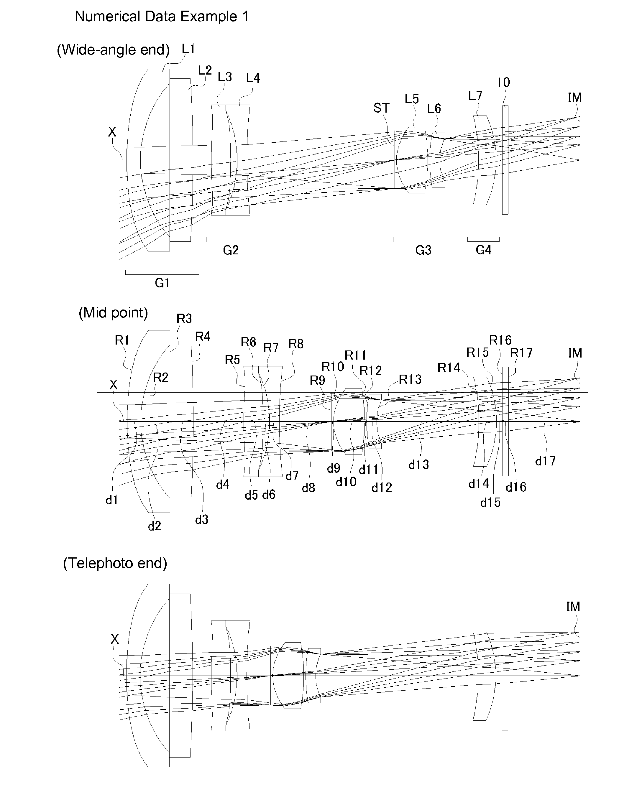
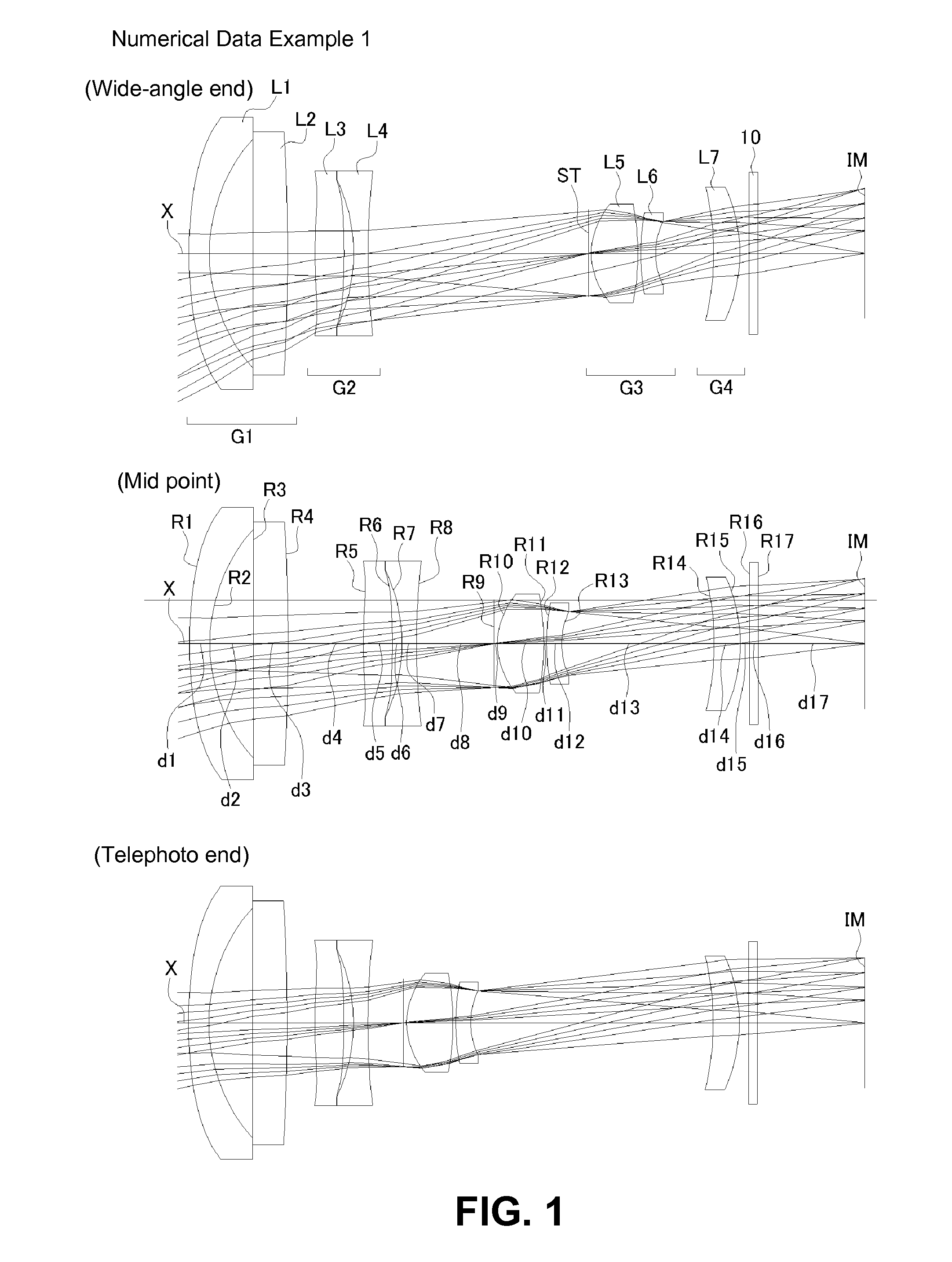
[0093]As shown in FIG. 1, the zoom lens of a first embodiment includes a first lens group G1 having negative refractive power; a second lens group G2 having negative refractive power; a third lens group G3 having positive refractive power; and a fourth lens group G4 having positive refractive power, arranged in the order from the object side. There is provided a cover glass 10 between the fourth lens group G4 and an image plane of an imaging element. The cover glass 10 may be optionally omitted (which will be also the same in a second and a third embodiments.)

[0094]In addition, in the zoom lens of the embodiment, the first lens group G1 and the fourth lens group G4 are fixed and the second lens group G2 and the third lens group G3 can move along the optical axis. Upon changing magnification from the wide-angle end to the telephoto end, the second lens group G2 first moves to the image plane side and then to the object side, and the third lens group G3 moves to the object side along ...

second embodiment

[0121]As shown in FIG. 11, similarly to the zoom lens of the first embodiment, the zoom lens of a second embodiment includes a first lens group G1 having negative refractive power; a second lens group G2 having negative refractive power; a third lens group G3 having positive refractive power; and a fourth lens group G4 having positive or negative refractive power, arranged in the order from the object side. There is provided a cover glass 10 arranged between the fourth lens group G4 and an image plane of an imaging element.

[0122]Also in the embodiment, the zoom lens is configured so that the first lens group G1 and the fourth lens group G4 are fixed and the second lens group G2 and the third lens group G3 move along the optical axis. The magnification changes as the third lens group G3 moves, and focusing and back focus adjustment work by moving the second lens group G2.

[0123]Here, according to the embodiment, the configuration of the first lens group G1 is different from that in th...

third embodiment

[0141]As shown in FIG. 26, similarly to the zoom lenses of the first and the second embodiments, the zoom lens of a third embodiment includes a first lens group G1 having negative refractive power; a second lens group G2 having negative refractive power; a third lens group G3 having positive refractive power; and a fourth lens group G4 having positive refractive power, arranged in the order from the object side. There is provided a cover glass 10 arranged between the fourth lens group G4 and an image plane of the imaging element.

[0142]The zoom lens of the embodiment is also configured so that the first lens group G1 and the fourth lens group G4 are fixed and the second lens group G2 and the third lens group G3 move along the optical axis. As the third lens group G3 moves, the magnification changes, and as the second lens group G2 move, focusing and back focus adjustment work.

[0143]Here, in the embodiment, the configuration of the third lens group G3 is different from those in the fi...


PUM


Abstract

A zoom lens includes a first lens group that has a lens having negative refractive power and a light path changing member; a second lens group that includes a lens having positive refractive power and a lens having negative refractive power, and has negative refractive power as a whole; a third lens group that includes a stop, a front group lens having positive refractive power, and a rear group lens having negative refractive power, and has positive refractive power as a whole; and a fourth lens group having positive or negative refractive power. Upon changing magnification from a wide-angle end to a telephoto end, the first lens group and the fourth lens group are fixed. The second lens group moves to the object side after the second lens group moves to an image side, and the third lens group linearly moves to the object side.

Description

CROSS-REFERENCE TO RELATED APPLICATIONS[0001]The application claims the benefit under 35 U.S.C. 119(e) of the provisional application No. 61 / 509,325, filed on Jul. 19, 2011.BACKGROUND OF THE INVENTION AND RELATED ART STATEMENT[0002]The present invention relates to a zoom lens for forming an image on an imaging element such as a CCD sensor and a CMOS sensor.[0003]In recent days, a zoom lens has been more frequently mounted on a small device such as a cellular phone, a portable information terminal, and an internet camera as well as a digital still camera for another additional value. In the zoom lens, a part of lenses or lens groups that compose a lens system moves along an optical axis thereof. Accordingly, it is possible to continuously change imaging magnification and successively increase and / or decrease an image of an object to various sizes.[0004]In case of mounting the zoom lens onto a small-sized device, the whole length of the zoom lens is preferably as short as possible. Ho...

Claims


Application Information

Patent Timeline
Patent Type & Authority Applications(United States)
IPC IPC(8): G02B15/14
CPCG02B15/177G02B15/144513G02B15/144505
Inventor KUBOTA, YOJI
Owner TOKYO VISIONARY OPTICS CO LTD
Why Eureka
Try Eureka