Pilot Fuel Injection for a Wave Rotor Engine

a pilot fuel injection and wave rotor technology, applied in the direction of machines/engines, mechanical equipment, lighting and heating apparatus, etc., can solve the problems of poor overall thermal efficiency, difficult integration with steady-flow machinery, and non-uniform outflow

a pilot fuel injection and wave rotor technology, applied in the direction of machines/engines, mechanical equipment, lighting and heating apparatus, etc., can solve the problems of poor overall thermal efficiency, difficult integration with steady-flow machinery, and non-uniform outflow

US20130236842A1Inactive Publication Date: 2013-09-12INDIANA UNIV RES & TECH CORP

Image

  • Pilot Fuel Injection for a Wave Rotor Engine
  • Pilot Fuel Injection for a Wave Rotor Engine
  • Pilot Fuel Injection for a Wave Rotor Engine

Examples


Embodiment Construction

[0051]For the purposes of promoting an understanding of the principles of the invention, reference will now be made to the embodiments illustrated in the drawings and specific language will be used to describe the same. It will nevertheless be understood that no limitation of the scope of the invention is thereby intended, such alterations and further modifications in the illustrated device, and such further applications of the principles of the invention as illustrated therein being contemplated as would normally occur to one skilled in the art to which the invention relates.

[0052]This application incorporates by reference the following documents: U.S. Pat. No. 5,894,719, published 20 Apr. 1999; U.S. Pat. No. 6,460,342, published October 2002; U.S. Pat. No. 6,526,936, published 4 Mar. 2003, U.S. Pat. No. 6,845,620, published 25 Jan. 2005; and U.S. Pat. No. 6,449,939, published 17 Sep. 2002.

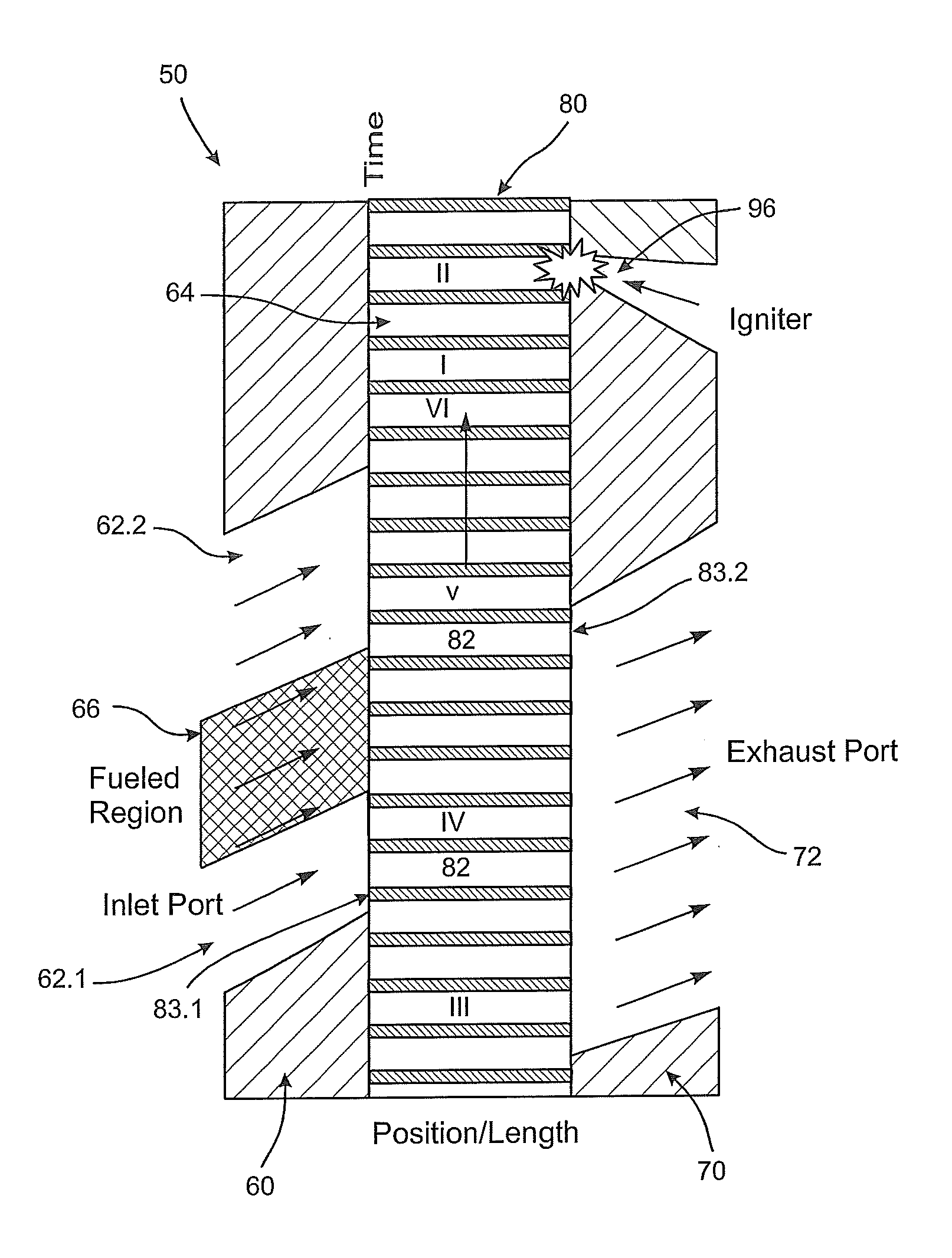
[0053]The present invention relates to apparatus and methods of pulsed or wave action combust...


PUM


Abstract

Apparatus and methods for combustion of fuel includes, in some embodiments, a fuel nozzle which injects fuel into a combustion channel of a wave rotor combustor or a pulse detonation combustor. In some embodiments the combustion process includes a backward-propagating detonation wave within a substantially closed channel which compresses discrete quantities of combustible and noncombustible mixture. Yet other embodiments include a precombustion chamber integrated into the wave rotor, the outlet stator or both.

Description

CROSS-REFERENCE TO RELATED APPLICATIONS[0001]This application is a divisional application of and claims priority to U.S. application Ser. No. 12 / 304,923, filed on Jul. 22, 2009, which is a national stage of PCT / US2007 / 071234, filed on Jun. 14, 2007, which claims priority to U.S. Provisional Patent Application Ser. No. 60 / 813,840, filed on Jun. 15, 2006, the contents of which are incorporated herein by reference.FIELD[0002]This invention relates generally to methods and apparatus for combustion, and in particular to combustion processes used with pulse detonation engines and wave rotors.BACKGROUND OF THE INVENTION[0003]The ability to produce pressure gain by a confined, intermittent combustion process (ideally constant-volume combustion) is a significant principle for improving gas turbine efficiencies. Indeed, the earliest working gas turbine around 1908, known as the Holzwarth engine, had valved and pulsating combustion chambers operated on a controlled explosive combustion process...

Claims


Application Information

Patent Timeline
12 Sep 2013
Publication
US20130236842A1
IPC
F23N1/02
CPC
F02C5/04; F02C7/222; F23N1/02; F23R7/00; F02C7/266
Inventors
NALIM, RAZI; PEZHMAN, AKBARI