Laser process alignment measuring method

a laser and process technology, applied in the direction of printing, recording apparatus, printed circuit aspects, etc., can solve the problems of laser inability to produce suitable register control and stage cannot produce such marks or traces in the base or carrier

Active Publication Date: 2013-12-12
TECNOMAR
View PDF12 Cites 6 Cited by
  • Summary
  • Abstract
  • Description
  • Claims
  • Application Information

AI Technical Summary

Problems solved by technology

A problem arising in this case is that, unlike the printing process stages, the laser process stage cannot produce any such marks or traces in the base or carrier material of the web, which could be utilised in register control.
It is often specifically the reel-to-reel manufacturing processes including a laser process stage that are the ones with a particularly great need for mutual alignment, or register control, of process stages, and thus the inability of the laser to produce a suitable mark for register control is a real problem.

Method used


Image

  • Laser process alignment measuring method
  • Laser process alignment measuring method

Examples


Embodiment Construction

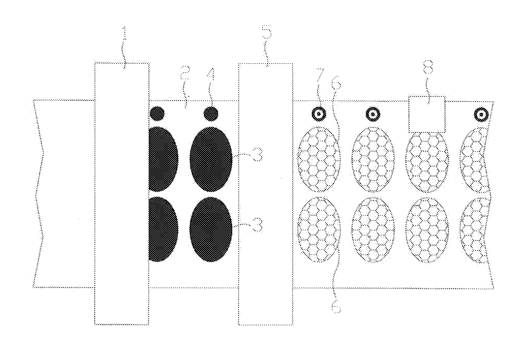
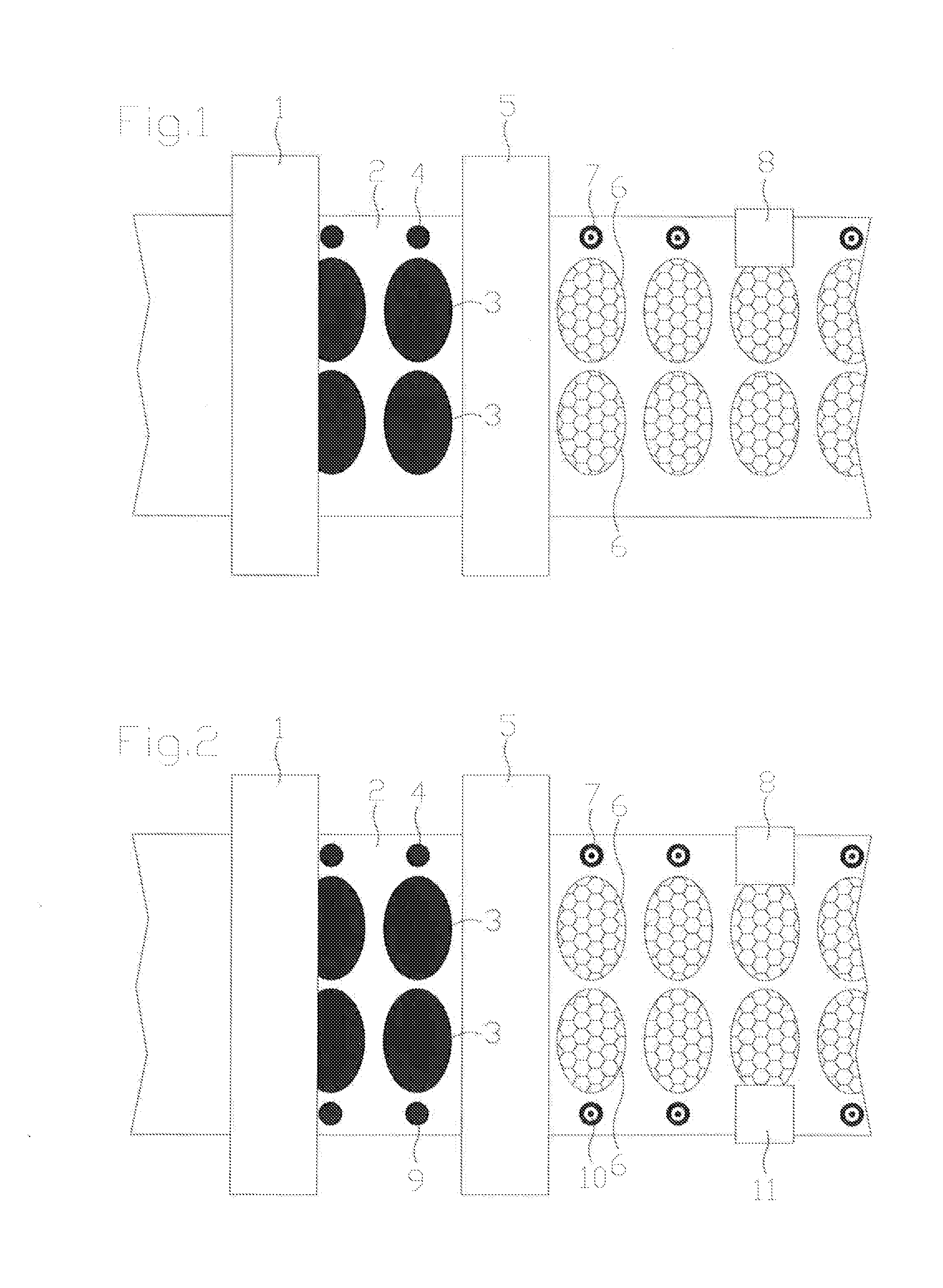
[0011]The method according to the invention is based on the technical solutions of commonly used laser process devices and register control systems, which makes the invention easy to implement.

[0012]The essence of the invention is that, on the basis of experience, even a laser which leaves hardly any or no marks on the base or carrier material of the web, plots a negative mark on a register mark made with printing ink. Here, a negative mark means that the printing ink can be accurately and easily removed with the laser, even down to the surface of the base or carrier material of the web, whereby a mark is created which is easily detectable by computer vision. The register mark is preferably printed in such a way that there is a good contrast between the mark and the base or carrier material of the web, and when the negative mark made by the laser reveals a part of the base or carrier material of the web under the printed register mark, the negative mark will also have a good contras...


PUM

PropertyMeasurementUnit
diameteraaaaaaaaaa
adhesiveaaaaaaaaaa
angleaaaaaaaaaa

Abstract

A laser process alignment measuring method applicable to a reel-to-reel manufacturing process including a laser process stage, wherein before at least one laser process stage, marks, patterns or surfaces (4,9) are made with printing ink on the base or carrier material of the web (2), and on which the laser beam used can make a mark (7, 10), for example, by removing or changing the printing ink, whereby at the laser process stage, another mark is plotted with the laser beam on the mark et al. printed with printing ink, and the position of the mark et al. printed with printing ink (4, 9) and the mark plotted with the laser (7, 10) are read optically to measure the alignment of the printing ink stage and the laser process stage.

Description

CROSS-REFERENCE TO RELATED APPLICATIONS[0001]The present application claims priority of Finnish Patent Application No. 20125633, filed Jun. 8, 2012, the contents of which are incorporated by reference herein.Technical Field of the Invention[0002]The invention relates to the precise mutual alignment, or register control, of laser processes or other processes used in reel-to-reel mass production.BACKGROUND OF THE INVENTION[0003]Many reel-to-reel manufacturing processes include one or more printing process stages, and for several successive printing process stages ready-made register control systems, are available which are based on the identification of marks printed in each printing unit by means of computer vision and on controlling the printing units on the basis of the observations made by the computer vision on the marks. A good register control system is capable of aligning printing process stages carried out in different units in such a way that, for example, a high-quality col...

Claims


Application Information

Patent Timeline
Patent Type & Authority Applications(United States)
IPC IPC(8): B41J2/045
CPCB41J2/04505B23K26/032B23K26/0846B41J11/46H05K1/0269H05K3/0008H05K3/0097H05K3/046H05K2201/0355H05K2201/09781H05K2201/09918H05K2203/0522H05K2203/107H05K2203/108H05K2203/1545B41F33/0081
Inventor MARTTILA, TOM
Owner TECNOMAR
Why Eureka
Try Eureka