

Call Movement in a Conferencing System
- Summary
- Abstract
- Description
- Claims
- Application Information
AI Technical Summary
Benefits of technology
Problems solved by technology
Method used
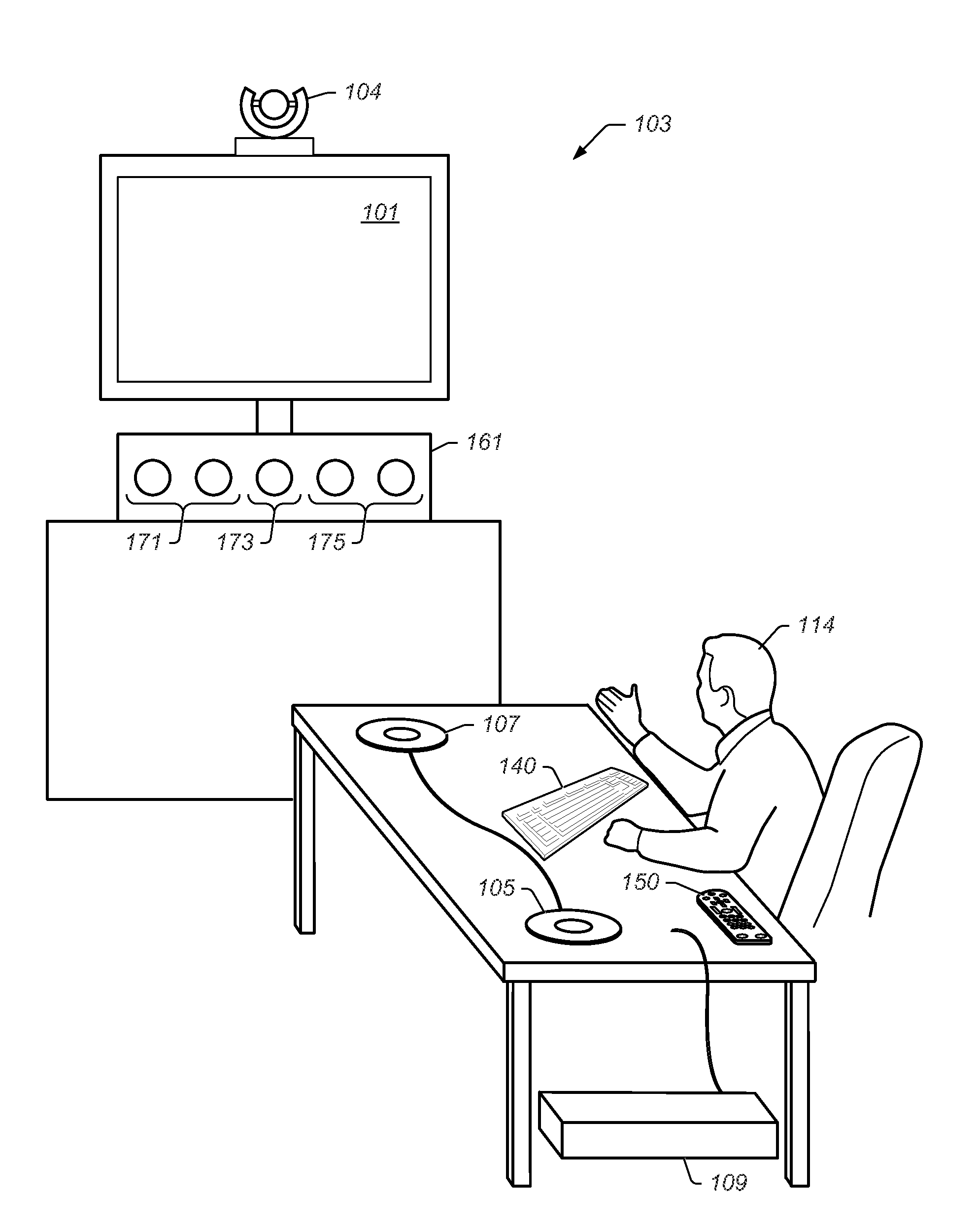
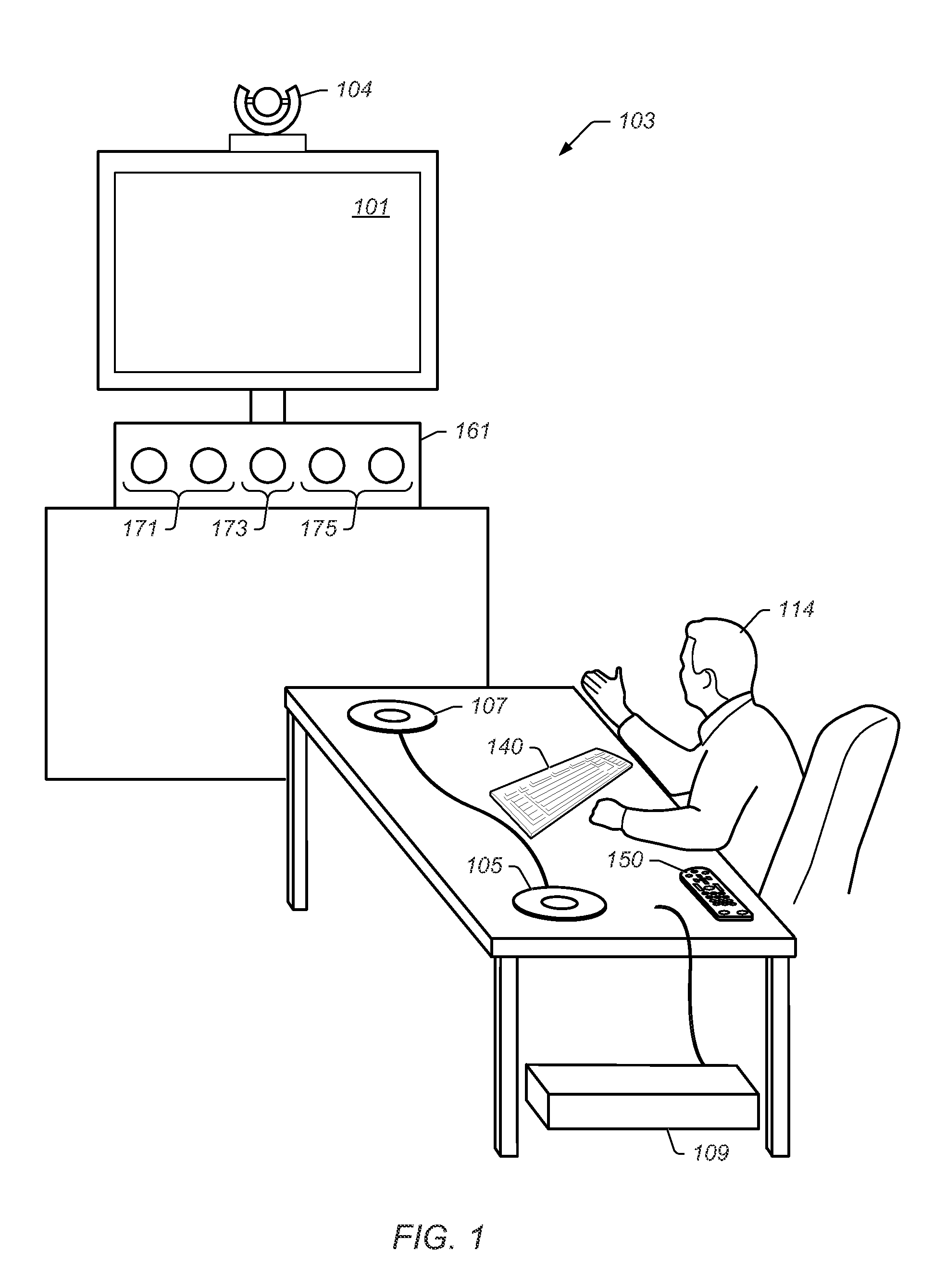
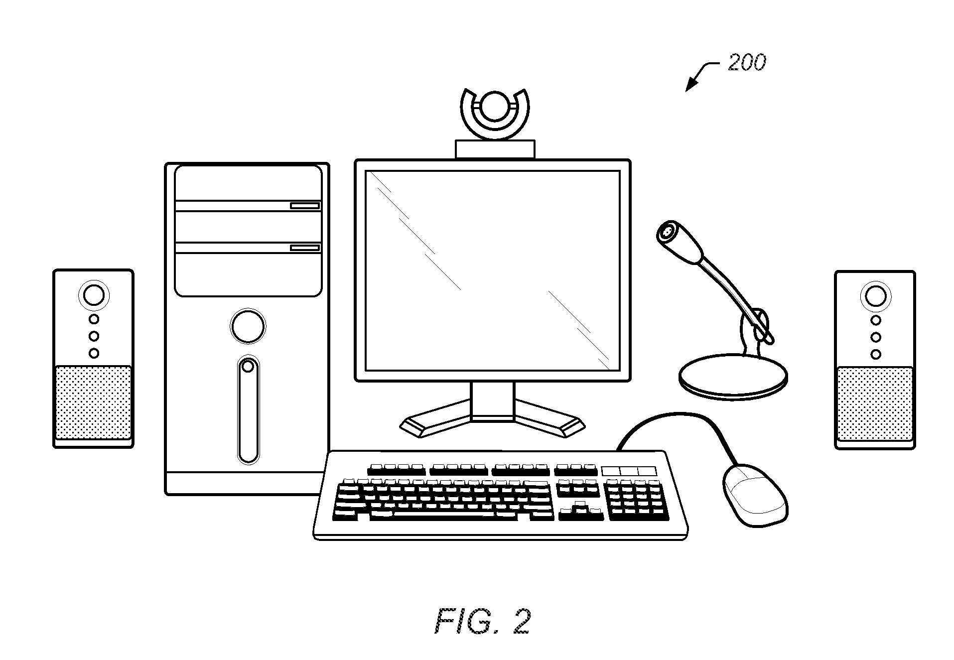
Image

Examples
Embodiment Construction
Incorporation by Reference
[0049]U.S. patent application titled “Video Conferencing System Transcoder”, Ser. No. 11 / 252,238, which was filed Oct. 17, 2005, whose inventors are Michael L. Kenoyer and Michael V. Jenkins, is hereby incorporated by reference in its entirety as though fully and completely set forth herein.[0050]U.S. patent application titled “Virtual Decoders”, Ser. No. 12 / 142,263, which was filed Jun. 19, 2008, whose inventors are Keith C. King and Wayne E. Mock, is hereby incorporated by reference in its entirety as though fully and completely set forth herein.[0051]U.S. patent application titled “Video Conferencing System which Allows Endpoints to Perform Continuous Presence Layout Selection”, Ser. No. 12 / 142,302, whose inventors are Keith C. King and Wayne E. Mock, is hereby incorporated by reference in its entirety as though fully and completely set forth herein.[0052]U.S. patent application titled “Video Conferencing Device which Performs Multi-way Conferencing”, Se...
PUM
 Abstract
Description
Claims
Application Information