Self-Propelled Civil Engineering Machine System With Field Rover

a self-propelled, civil engineering machine technology, applied in the direction of distance measurement, instruments, ways, etc., can solve the problems of a large amount of technical cost and complication, the use of guiding wires or lines is found to be disadvantageous, and the plotting is particularly costly and complicated, etc., to achieve any great cost or complication in the plotting, and high accuracy

Active Publication Date: 2014-04-17
WIRTGEN GMBH
View PDF5 Cites 5 Cited by
  • Summary
  • Abstract
  • Description
  • Claims
  • Application Information

AI Technical Summary

Benefits of technology

[0012]The object underlying the invention is therefore to provide a self-propelled civil engineering machine, and in particular a road milling machine, a road paver or a slipform paver, which can move automatically, without any great cost or complication in the plotting of position and with high accuracy, along a desired curve extending for relatively short distances of travel and having tight radiuses. Another object is to specify a method which allows a self-propelled civil engineering machine to be controlled automatically, without any great cost or complication in the plotting of position and with high accuracy, along a desired curve extending for relatively short distances of travel and having tight radiuses.

Problems solved by technology

When self-propelled civil engineering machines are controlled automatically, the problem arises that a preset reference point on the civil engineering machine has to move precisely along a preset curve in space on the ground, in order for example to enable a structure of a preset shape to be produced on the ground in the correct position and in the correct orientation.
However, the use of a guiding wire or line is found to be a disadvantage when structures of small dimensions, such as cigar-shaped traffic islands for example, which are distinguished by extending for small distances and having tight radiuses, are to be produced.
It is a disadvantage that the plotting of the position of an object using a master measurement system to control the civil engineering machine calls for a great deal of technical cost and complication because the construction project will be complex and the object has to be fitted into it.
What is particularly costly and complicated is the plotting which has to be done of the positions of various reference points in the measurement system.
This cost and complication can only be justified for large objects.
For small objects on the other hand the cost and complication is disproportionately high.
Another disadvantage of the objects being fitted into the complex building project lies in the fact that in practice, with small objects, allowance often has to be made for fixed points, such for example as existing hydrants or water outlets on the site, which may possibly not be situated precisely at the points at which they were entered in the plans.

Method used


Image

  • Self-Propelled Civil Engineering Machine System With Field Rover
  • Self-Propelled Civil Engineering Machine System With Field Rover
  • Self-Propelled Civil Engineering Machine System With Field Rover

Examples


Embodiment Construction

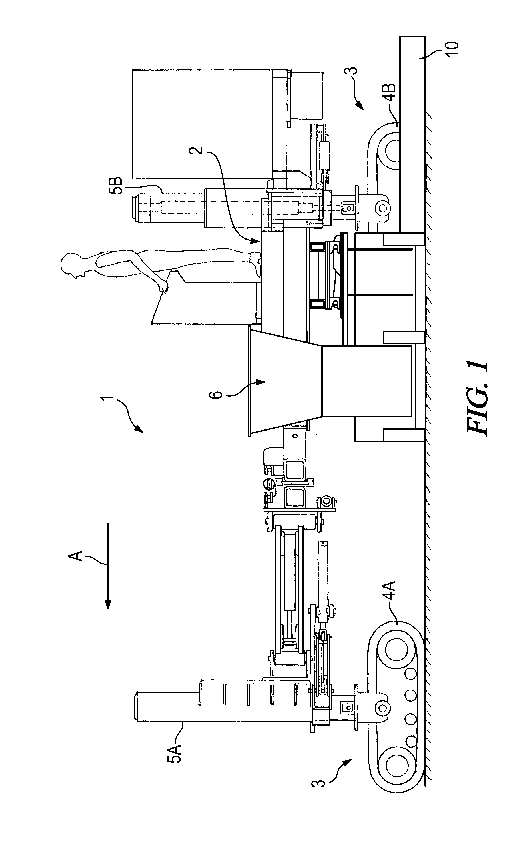
[0056]FIG. 1 is a side view of, as an example of a self-propelled civil engineering machine, a slipform paver which is described in detail in EP 1 103 659 B1 (U.S. Pat. No. 6,481,924). Because slipform pavers as such are part of the prior art, all that will be described here are those components of the civil engineering machine which are material to the invention.

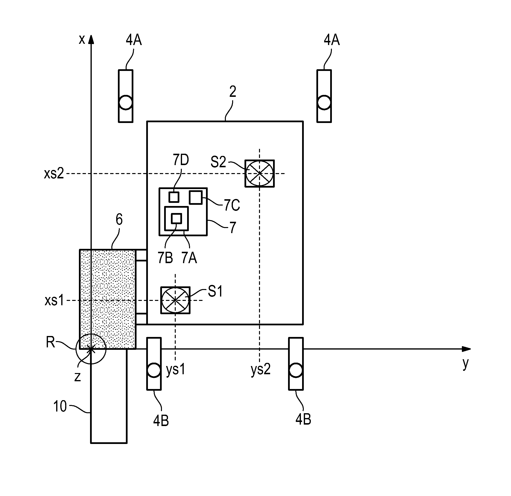
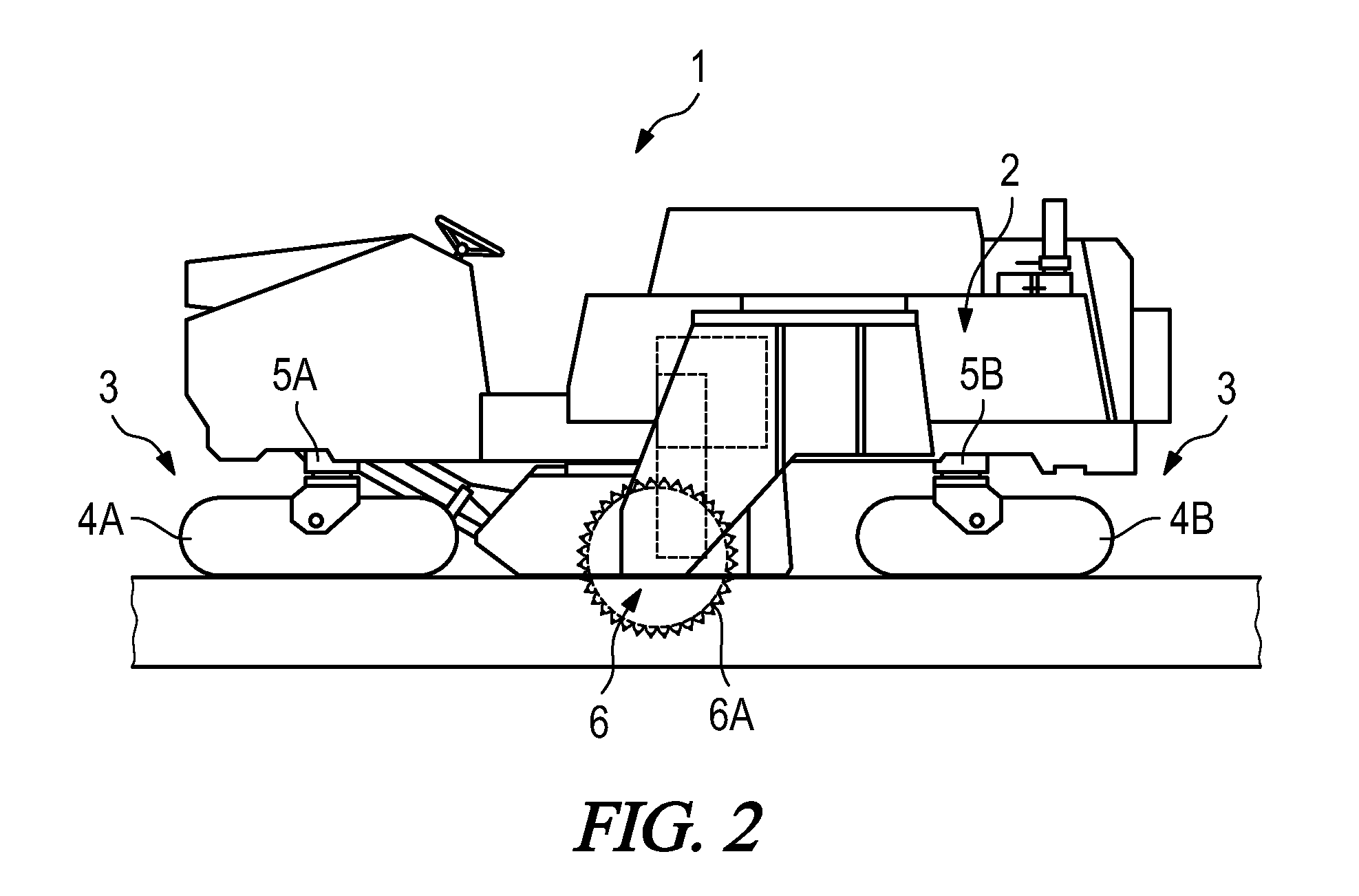
[0057]The slipform paver 1 has a chassis 2 which is carried by running gear 3. The running gear 3 has two front and two rear track-laying running gear units 4A, 4B which are fastened to front and rear lifting pillars 5A, 5B. The direction of working (direction of travel) of the slipform paver is identified by an arrow A.

[0058]The track-laying running gear units 4A, 4B and the lifting pillars 5A, 5B are parts of a drive unit of the slipform paver which has drive means to allow the civil engineering machine to carry out movements in translation and / or rotation on the ground. By raising and lowering the lifting pillars 5A, 5B,...


PUM


Abstract

A civil engineering machine has a machine control unit configured to determine data which defines the position and/or orientation of a reference point on the civil engineering machine in relation to a reference system independent of the position and orientation of the civil engineering machine. A geometrical shape to be produced on the ground is preset in either a machine control unit or a field rover control unit. The field rover is used to determine a position of at least one identifiable point of the preset geometrical shape in the independent reference system. Curve data defining a desired curve in the independent reference system, corresponding to the preset shape, is determined at least partially on the basis of the position of the at least one identifiable point of the preset geometrical shape in the independent reference system.

Description

BACKGROUND OF THE INVENTION[0001]The invention relates to a self-propelled civil engineering machine, and in particular a road milling machine, road paver or slipform paver, and to a method of controlling a self-propelled civil engineering machine and in particular a road milling machine, road paver or slipform paver.DESCRIPTION OF THE PRIOR ART[0002]There are a variety of known kinds of self-propelled civil engineering machines. In particular, these machines include the known slipform pavers, road pavers and road milling machines. The characteristic feature of these self-propelled civil engineering machines is that they have a working unit having working means for producing structures on the ground or for making changes to the ground.[0003]In the known slipform pavers, the working unit comprises an arrangement for moulding flowable material and in particular concrete, which arrangement will be referred to in what follows as a concrete mould. Structures of different types, such as c...

Claims


Application Information

Patent Timeline
Patent Type & Authority Applications(United States)
IPC IPC(8): E01C19/00G01C15/00
CPCG01C15/00E01C19/004E01C23/088E01C19/42G05D1/0278G05D2201/0202G01C15/06
Inventor FRITZ, MATTHIASBARIMANI, CYRUSHAHN, GUNTERBERNING, CHRISTIAN
Owner WIRTGEN GMBH
Why Eureka
Try Eureka