

Power tools with housings having integral resilient motor mounts
a technology of resilient motors and power tools, applied in the field of power tools, can solve problems such as undesired vibration, and achieve the effect of reducing vibration transmitted
- Summary
- Abstract
- Description
- Claims
- Application Information
AI Technical Summary
Benefits of technology
Problems solved by technology
Method used
Image

Examples
Embodiment Construction
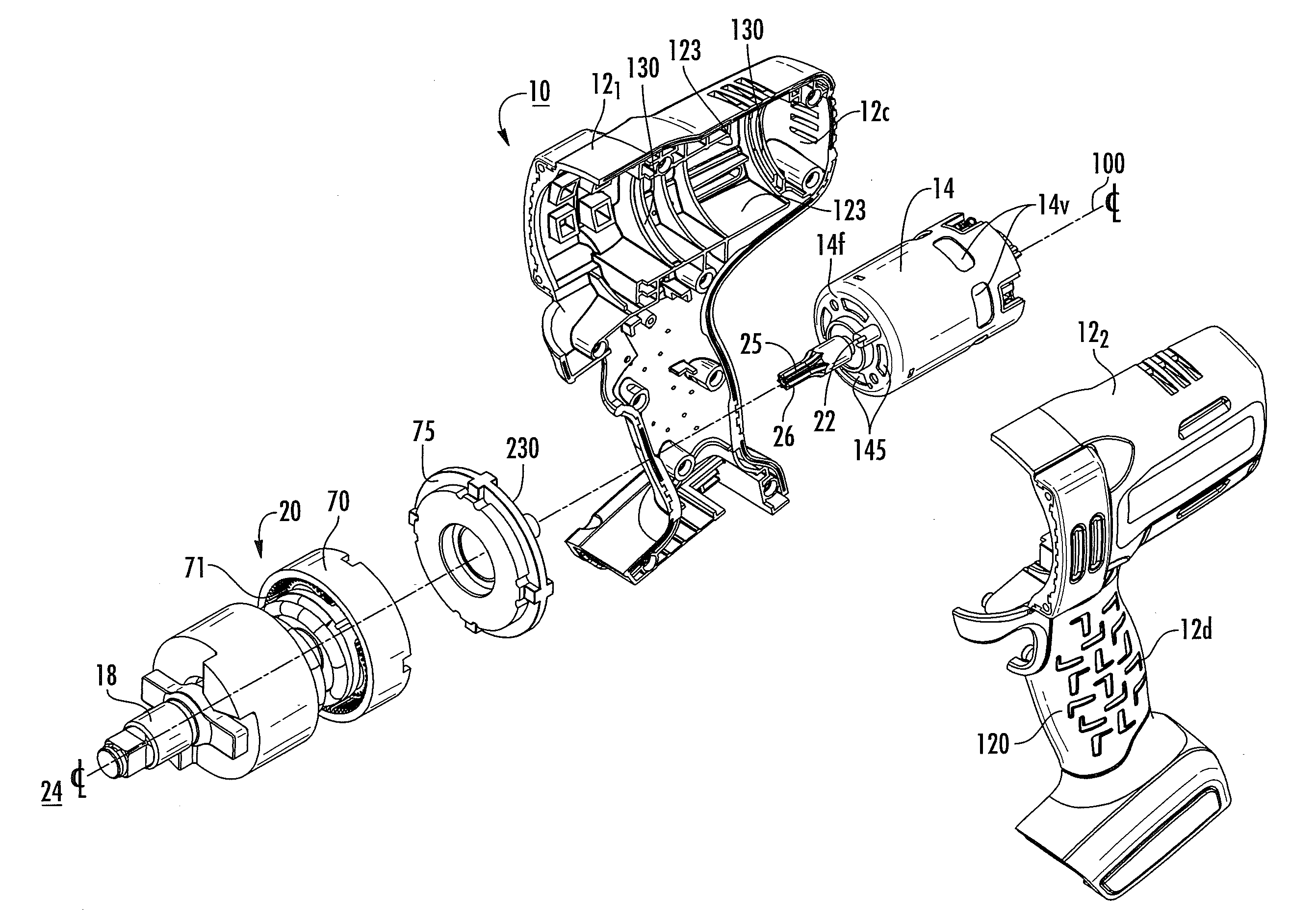
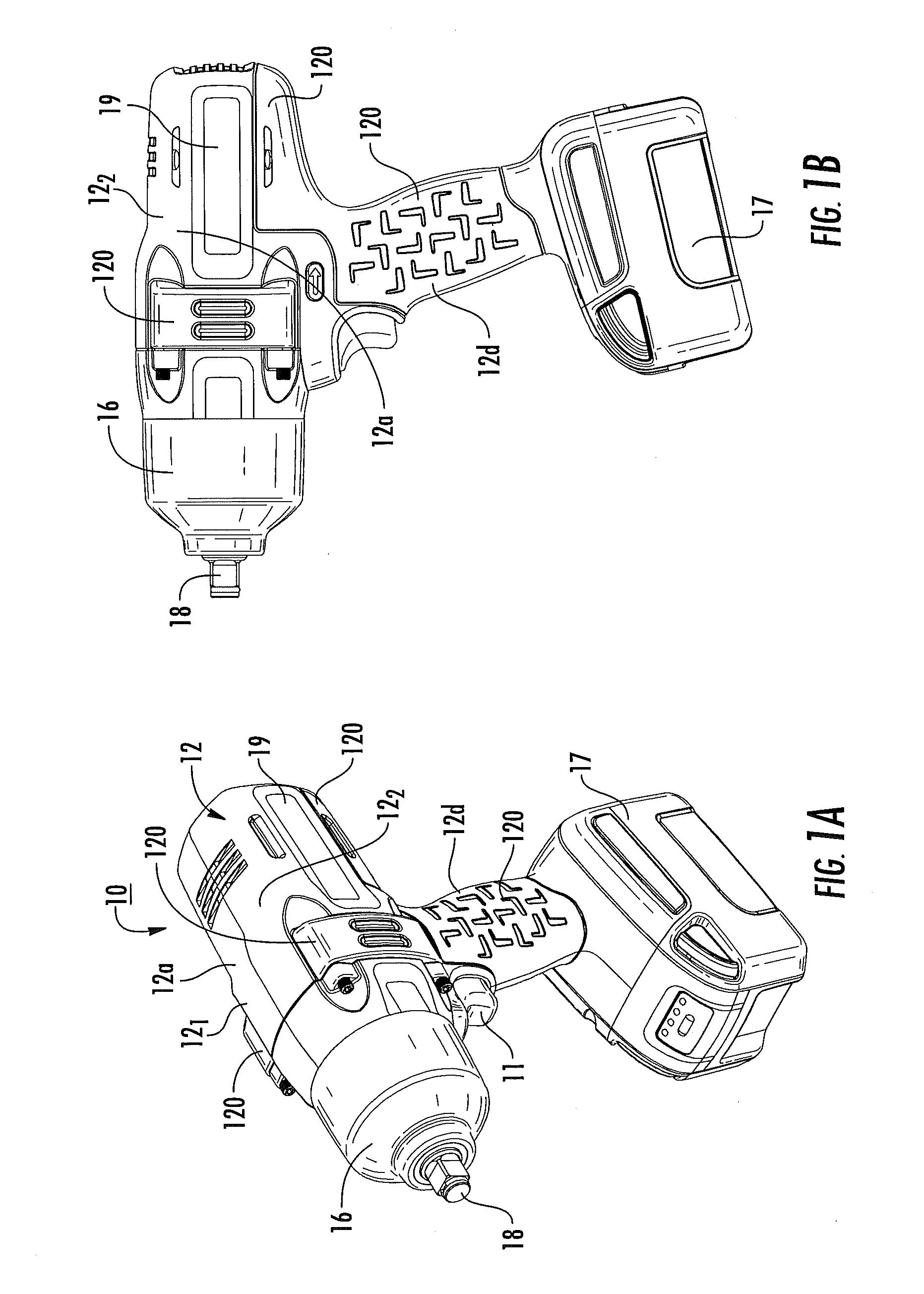
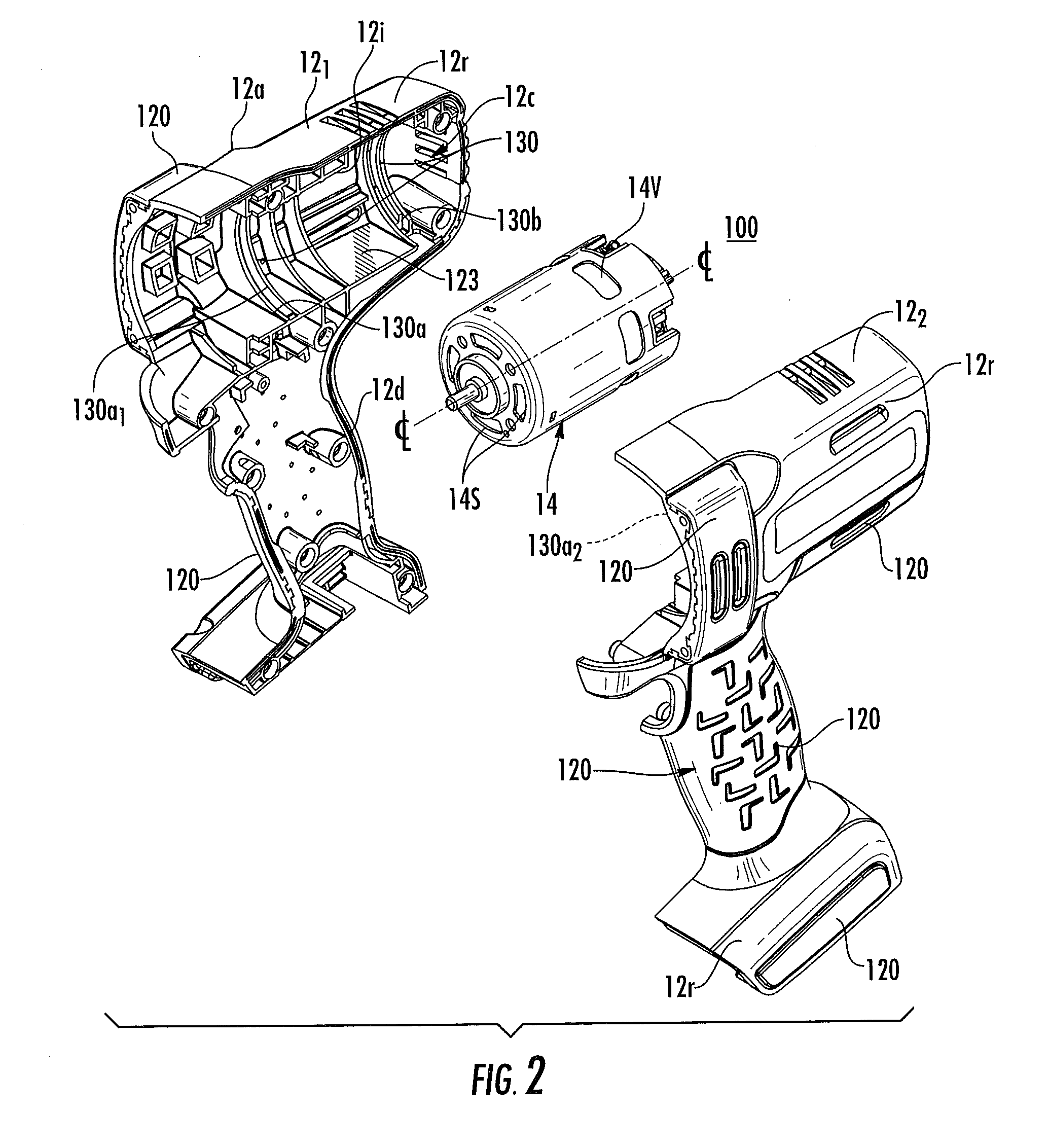
[0003]Embodiments of the invention are directed to providing housings with integral, resilient (e.g., elastomeric or rubber) overmold motor mounts that can reduce vibration transmitted between the housing and motor.
[0004]Some embodiments are directed to a power tool housing. The housing includes first and second housing shells that each have an outer wall that encases inner surfaces. The housing shells matably attach to each other and define an interior motor cavity that is sized and configured to encase at least a motor associated with a power train for a power tool. Each housing shell is a substantially rigid molded shell body. Each housing shell includes a plurality of axially spaced apart overmold motor mount member portions comprising a resilient material that are directly, integrally attached to at least one inner surface of the respective housing shell. One or sets of the axially spaced apart overmold motor mount member portions of each shell are aligned and cooperate to defi...
PUM
| Property | Measurement | Unit |
|---|---|---|
| width | aaaaa | aaaaa |
| distance | aaaaa | aaaaa |
| width | aaaaa | aaaaa |
Abstract
Description
Claims
Application Information