Control circuit for electric power circuit switch

a control circuit and power circuit technology, applied in the direction of emergency protective circuit arrangements, electrical devices, emergency protection circuit arrangements, etc., can solve the problems of large damage and reduced frequency

Active Publication Date: 2014-09-18
LSIS CO LTD
View PDF10 Cites 14 Cited by
  • Summary
  • Abstract
  • Description
  • Claims
  • Application Information

AI Technical Summary

Benefits of technology

[0012]Therefore, an aspect of this disclosure is to provide a control circuit for an electric power circuit switch capable of determining whether a fault current has occurred by using a DFT in a current region in which whether a fault current is has occurred is not requi

Problems solved by technology

When a short-circuit, or the like, occurs, very low impedance as low as line impedance of a fault spot is formed in a generator or a bus line, and thus, a very large short-circuit current flows in the electric power system (hereinafter, referred to as a ‘system’), which results in that the system suffers various problems such as a voltage

Method used


Image

  • Control circuit for electric power circuit switch
  • Control circuit for electric power circuit switch
  • Control circuit for electric power circuit switch

Examples


Embodiment Construction

[0027]Description will now be given in detail of the exemplary embodiments, with reference to the accompanying drawings. For the sake of brief description with reference to the drawings, the same or equivalent components will be provided with the same reference numbers, and description thereof will not be repeated.

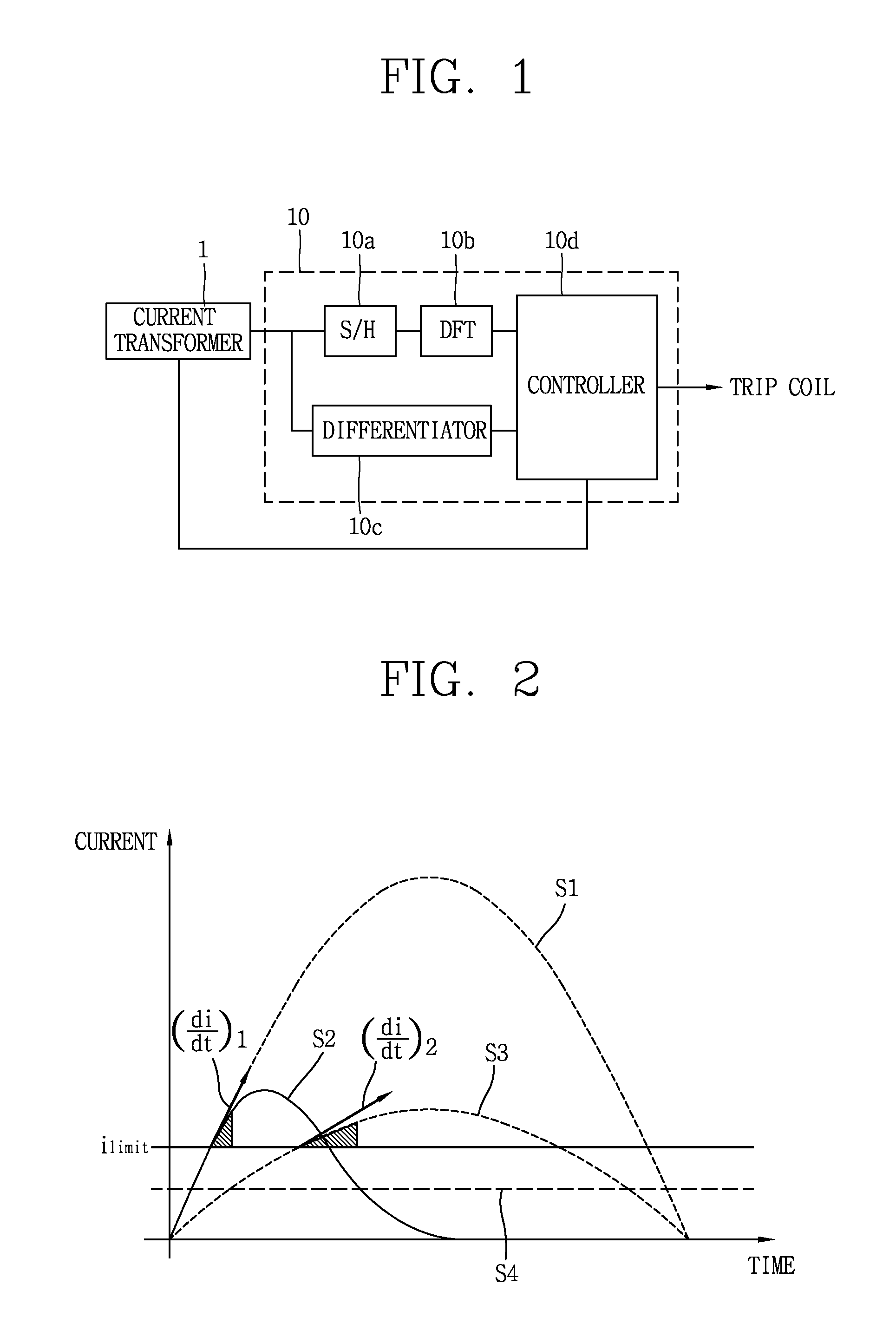
[0028]Referring to FIG. 1 as a functional block diagram illustrating a configuration of a control circuit for an electric power circuit switch according to a preferred embodiment of the present invention, a control circuit 10 for an electric power circuit switch according to a preferred embodiment of the present invention includes a sampling / hold circuit section (in other words sampling and hold circuit section, can be abbreviated as S / H) 10a, a Discrete Fourier Transforming (abbreviated as DFT hereinafter) circuit section 10b, a differentiator 10c, and a controller 10d.

[0029]The sampling / hold circuit section 10a samples one period of a detection signal of an electric cur...


PUM


Abstract

A control circuit for an electric power circuit switch includes: a sampling/hold circuit section configured to sample a period of a detection signal of a current of an electric power system and provide a sampled signal; a discrete Fourier transforming (abbreviated as DFT) circuit section perform DFT on the one-period sampled signal to provide a magnitude and a phase of a frequency component of the current of the electric power system; a differentiator configured to differentiate the detection signal to provide a rate of change of the current over time; and a controller to determine whether to perform trip controlling according to the magnitude of the frequency component of the current from the DFT circuit section or the rate of change from the differentiator on the basis of the rate of change of the current and the reference rate of change.

Description

CROSS-REFERENCE TO RELATED APPLICATION[0001]Pursuant to 35 U.S.C. §119(a), this application claims the benefit of earlier filing date and right of priority to Korean Application No. 10-2013-0026933, filed on Mar. 13, 2013, the contents of which is incorporated by reference herein in its entirety.BACKGROUND OF THE INVENTION[0002]1. Field of the Invention[0003]The present disclosure relates to a control circuit for an electric power circuit switch, and particularly, to a control circuit for an electric power circuit switch capable of reducing a control speed of a switch in response to detection of a current flowing in the electric power circuits.[0004]2. Background of the Invention[0005]An electric power system, which generates and consumes electric power, includes an electric power transmission network, substation, and an electric power distribution network between a power plant and consumers.[0006]Various devices are applied to respective components of the electric power system to p...

Claims


Application Information

Patent Timeline
IPC IPC(8): H02H3/08
CPCH02H3/08H02H3/44H02H3/46
Inventor JEONG, YOUNG WOO
Owner LSIS CO LTD
Why Eureka
Try Eureka