Compact vertical-motion isolator

a vertical-motion isolator and compact technology, applied in the direction of springs/dampers functional characteristics, machine supports, other domestic objects, etc., can solve the problems of increasing the damping inherent in the structure, reducing the vertical or horizontal stiffness, etc., to remove the positive stiffness, and reduce the overall width of the vertical-motion isolator

Active Publication Date: 2015-05-07
MINUS K TECH
View PDF2 Cites 1 Cited by
  • Summary
  • Abstract
  • Description
  • Claims
  • Application Information

AI Technical Summary

Benefits of technology

[0008]The present invention provides novel and significant improvements in the design of vertical-motion isolators which utilize a negative-stiffness-producing mechanism that includes compressible flexures that can be loaded to exceed their point of elastic instability and thereby remove positive stiffness from a support spring. The present invention provides an arrangement of these flexures such that the size of the isolator can be compacted without compromising the vibration isolating performance of the isolator. In this regard, the present invention provides a “stacked” or “side-by-side” arrangement of the flexures whereby the assemblage of flexures can reduce the overall width of the vertical-motion isolator since the lengths of each flexure overlies the lengths of the other flexure(s) while still allowing the flexures to be operatively connected together to permit the negative-stiffness-producing mechanism to simultaneously compress each flexure to exceed its point of elastic instability and remove stiffness from the support spring.

Problems solved by technology

There are, however, shortcomings and disadvantages associated with these particular prior art isolation systems which prevent them from obtaining low system natural frequencies and from limiting internal structural resonant responses to low values while providing high isolation performance at the higher frequencies.
This loading to approach the point of elastic instability, also called the “critical buckling load” of the structure, causes a substantial reduction of either the vertical or the horizontal stiffness of the isolator to create an isolation system that has low stiffness in the vertical and in any horizontal direction, and increases the damping inherent in the structure.

Method used


Image

  • Compact vertical-motion isolator
  • Compact vertical-motion isolator
  • Compact vertical-motion isolator

Examples


Embodiment Construction

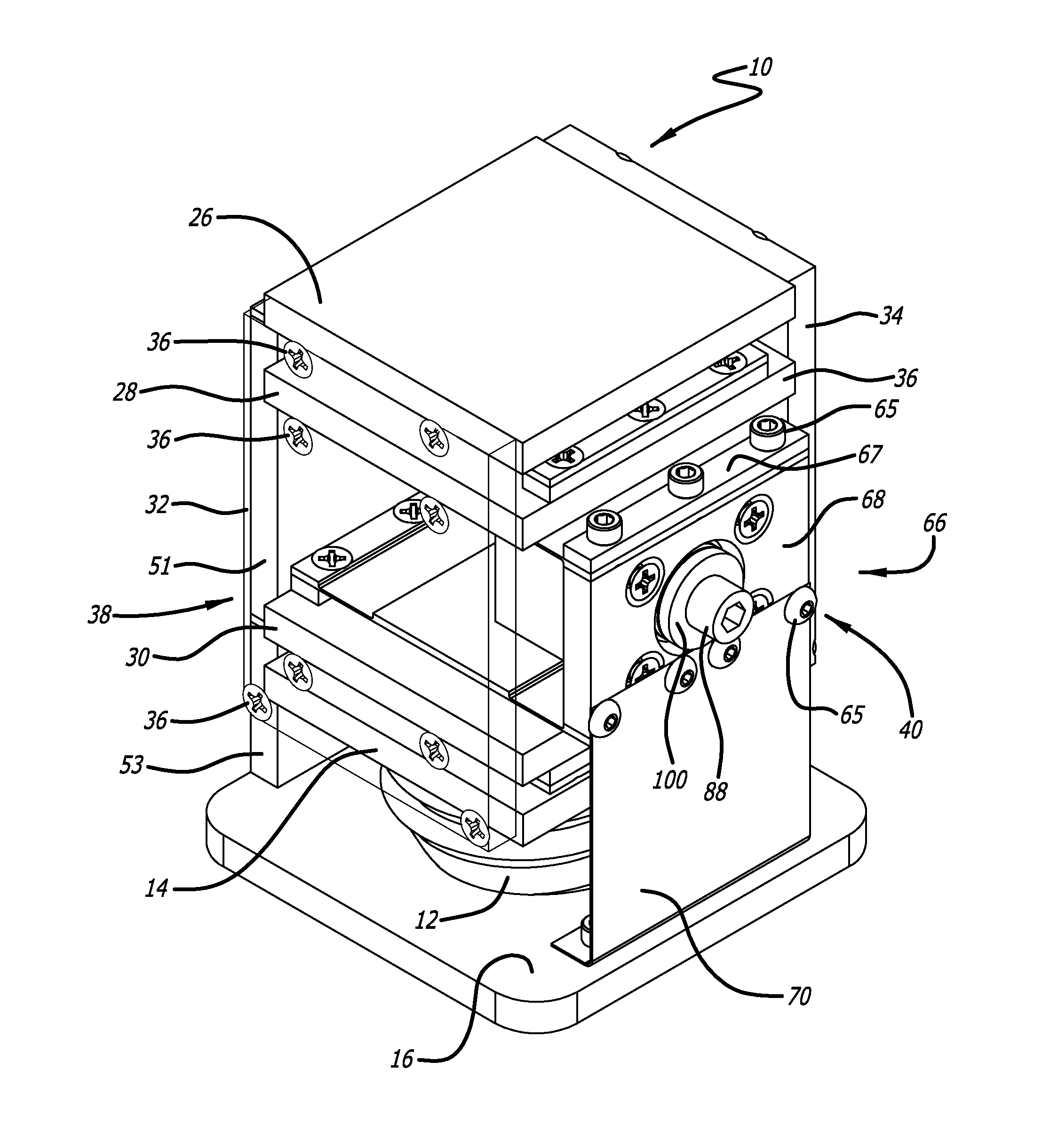
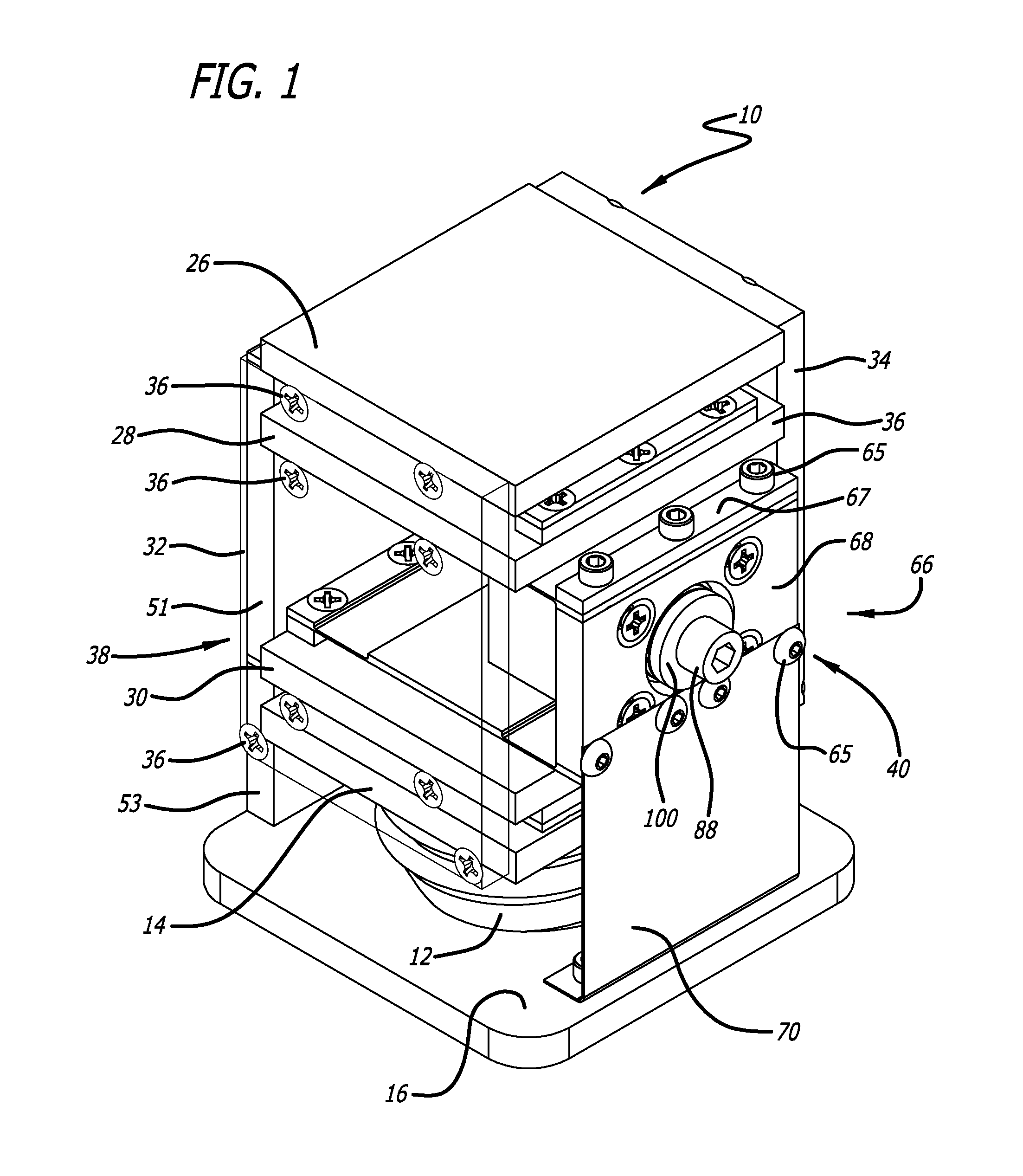
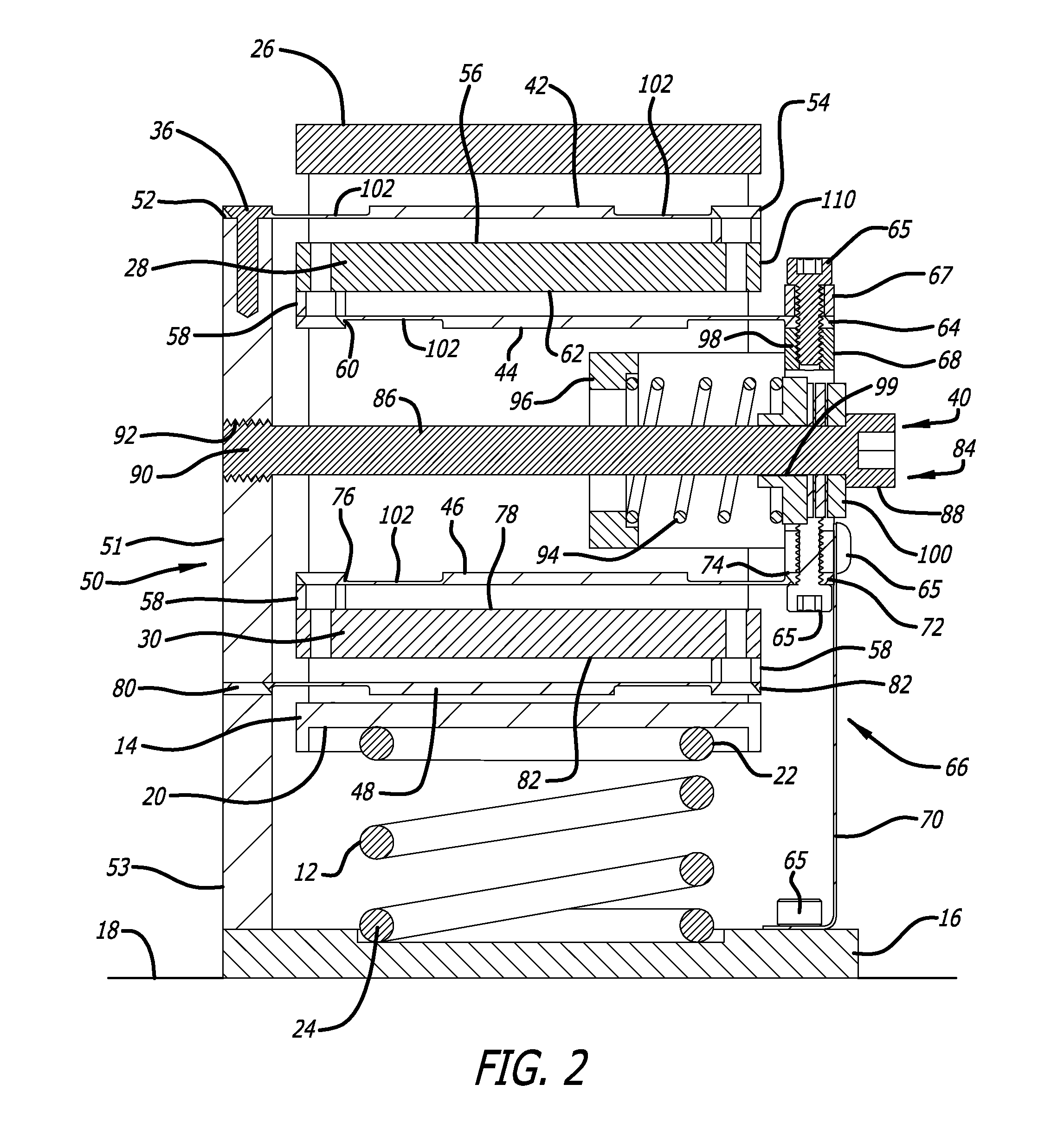
[0031]FIGS. 1-5 show one embodiment of a compact vertical-motion isolator 10 made in accordance with the present invention. The embodiment of the vertical-motion isolator 10 of FIGS. 1-5 is designed to support a payload (not shown) relative to a foundation to reduce the transmission of axial or vertical vibrations (motion) between the payload and foundation.

[0032]The compact vertical-motion isolator 10 of the present invention includes a support member in the form of a main support spring 12 that is operatively connected between an upper spring support 14 and a base platform 16 that sits on the foundation 18. This base platform 16 may include leveling screws (not shown) which could be used for leveling the base platform 16 relative to the foundation 18. The upper spring support 14 includes a recess 20 for receiving one end 22 of the support spring 12. The other end 24 of the support spring 12 remains in contact with the base platform 16.

[0033]A top mounting plate 26 is coupled to th...


PUM


Abstract

A vertical-motion vibration isolator utilizes negative-stiffness-producing mechanism which includes a plurality of compressed flexures, each having a particular length in the compressed direction of the flexure and being oriented in a horizontal direction, wherein the plurality of compressed flexures are positioned relative to each other such that the length of each compressed flexure substantially overlaps the length of each of the other compressed flexures. At least some of the plurality of compressed flexures can be positioned in a stacked arrangement. The arrangement of compressed flexures forming a portion of the negative-stiffness mechanism can reduce the size of the isolator without compromising vibration isolation performance.

Description

BACKGROUND OF THE INVENTION[0001]The present invention relates generally to suspension systems for isolating and reducing the transmission of vibratory motion between an object or payload and a base and, more particularly, to a compact vibration isolator which exhibits low stiffness in the direction of the weight load to effectively reduce the transmission of vibrations between the object and the base. The present invention represents improvements over my previous isolators which utilize negative-stiffness mechanisms to produce low vertical natural frequencies and which rely on a principle of loading a particular elastic structure which forms the isolator or a portion of it to approach the elastic structure's point of elastic instability.[0002]The problems caused by unwanted vibration on equipment, devices and processes that are extremely motion sensitive have been widely researched and numerous solutions to prevent or reduce the transmission of vibratory motion have been proposed a...

Claims


Application Information

Patent Timeline
Patent Type & Authority Applications(United States)
IPC IPC(8): F16F3/10F16F15/04
CPCF16F15/046F16F3/10F16F3/02F16F2228/063F16F15/04
Inventor PLATUS, DAVID L.
Owner MINUS K TECH
Why Eureka
Try Eureka