Method of manufacturing gear and forging apparatus for manufacturing gear

Active Publication Date: 2015-05-14
HONDA MOTOR CO LTD
View PDF4 Cites 3 Cited by
  • Summary
  • Abstract
  • Description
  • Claims
  • Application Information

AI Technical Summary

Benefits of technology

[0024]Since the damping mechanisms are employed in the present invention, the external teeth are machined and the internal teeth are formed at different times. Therefore, it is easy to control the flow of the material of the workpiece.
[0025]Thus, the workpiece is lowered along the internal tooth forming die while being restrained by the pressing die and the external tooth machining die. At this time the internal teeth are formed, and thus the forming accuracy is enhanced. Therefore, the gear (forged product) can be manufactured with excel

Problems solved by technology

However, it is not easy for the disclosed forging process to control the flow of the workp

Method used


Image

  • Method of manufacturing gear and forging apparatus for manufacturing gear
  • Method of manufacturing gear and forging apparatus for manufacturing gear
  • Method of manufacturing gear and forging apparatus for manufacturing gear

Examples


Embodiment Construction

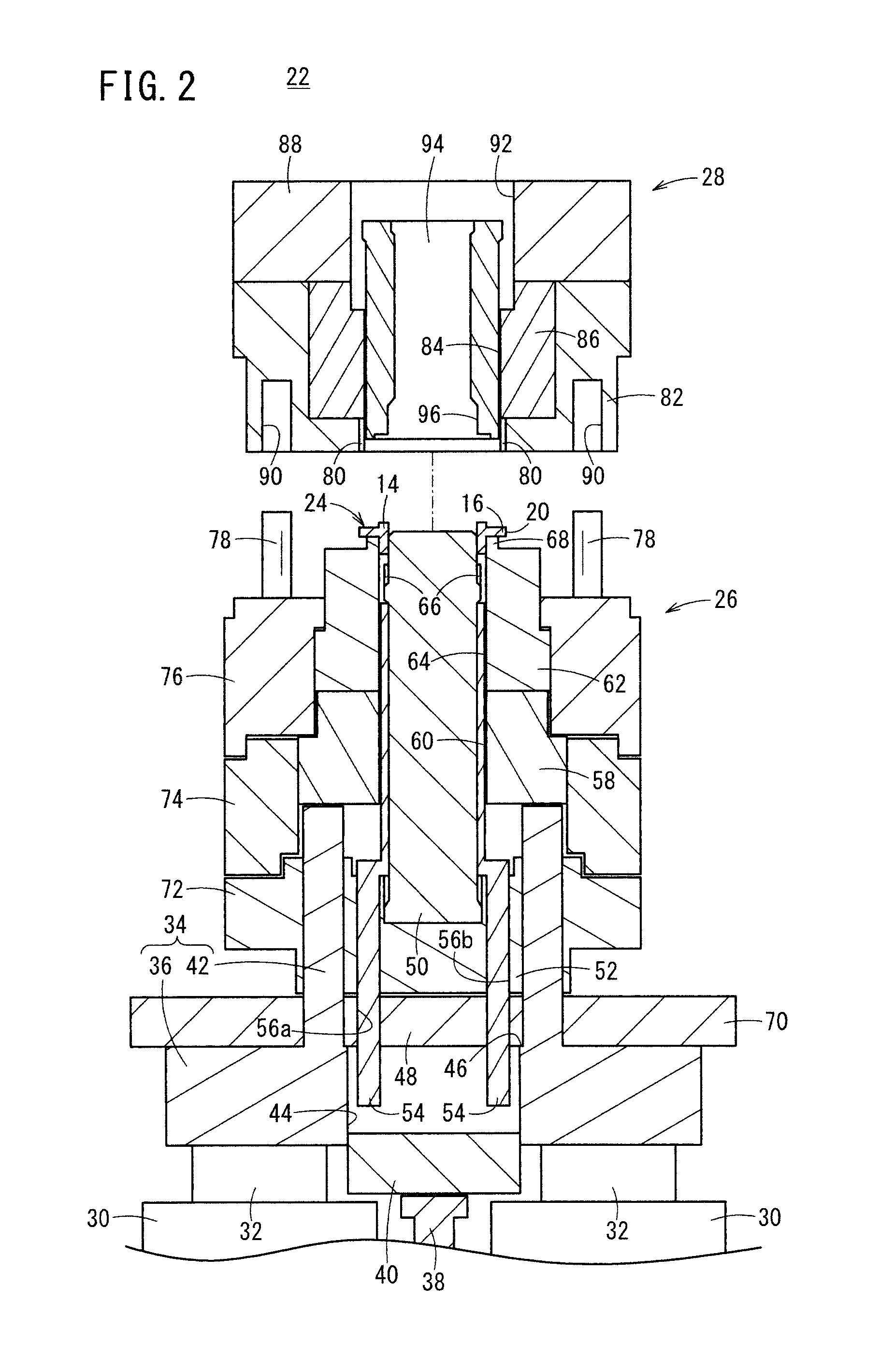
[0041]A method of manufacturing a gear according to a preferred embodiment of the present invention in relation to a forging apparatus for carrying out the method will be described in detail below with reference to the accompanying drawings.

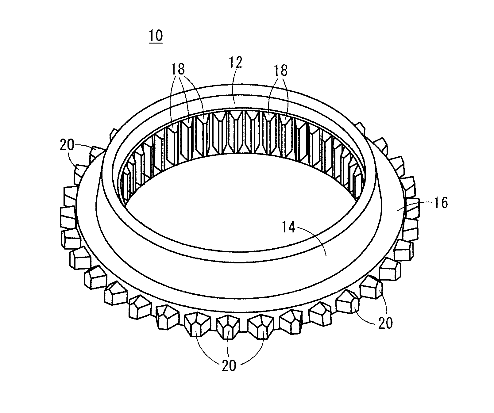
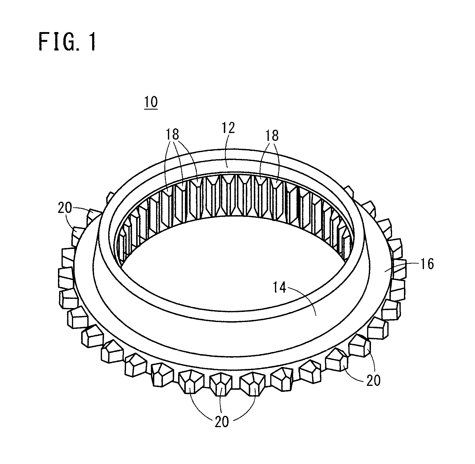
[0042]A gear as a forged product will be described below with reference to FIG. 1. As shown in FIG. 1, a gear 10 has a short hollow cylinder 14 with a through hole 12 defined therein and a flange 16 projecting radially outwardly from an end portion of the hollow cylinder 14. The hollow cylinder 14 has a plurality of splines 18 disposed on an inner circumferential wall surface thereof. The splines 18 each extend straight along a heightwise direction (axial direction) of the hollow cylinder 14.

[0043]The flange 16 has a plurality of so-called dog teeth 20 disposed on an outer circumferential wall surface thereof. The gear 10 is thus in the form of a hollow body with the splines 18 formed as internal teeth and the dog teeth 20 as external teeth. The ...


PUM


Abstract

A forging apparatus carries out a method of manufacturing a gear having external teeth on an outer circumferential wall surface thereof and internal teeth on an inner circumferential wall surface thereof. First, an internal tooth forming die is inserted through a through hole defined in a workpiece. Next, a pressing die is caused to abut against the workpiece, and an external tooth machining die finishes the external teeth while preventing a support die from being lowered under action of damping mechanisms. Thereafter, a pressing die presses the workpiece to apply a load in excess of a preset load for the damping mechanisms. The support die is then lowered to lower the workpiece along the internal tooth forming die. At this time, the internal teeth are formed on the inner circumferential wall surface of the workpiece.

Description

CROSS-REFERENCE TO RELATED APPLICATION[0001]This application is based upon and claims the benefit of priority from Japanese Patent Application No. 2013-231682 filed on Nov. 8, 2013, the contents of which are incorporated herein by reference.BACKGROUND OF THE INVENTION[0002]1. Field of the Invention[0003]The present invention relates to a method of manufacturing a gear having a plurality of external teeth on an outer circumferential wall surface thereof and a plurality of internal teeth on an inner circumferential wall surface thereof, and a forging apparatus for manufacturing such a gear.[0004]2. Description of the Related Art[0005]Gears that have external teeth on an outer circumferential wall thereof and internal teeth on an inner circumferential wall thereof are used in some applications. In this case, for example, the internal teeth are held in mesh with teeth on a circumferential side wall of a shaft member, thereby coupling the gear to the shaft member. Therefore, a process of...

Claims


Application Information

Patent Timeline
IPC IPC(8): B21J13/02B21K1/30B21J13/08B21J5/02
CPCB21J13/02B21J13/08B21K1/30B21J5/025B21J5/022Y10T29/49474
Inventor OZEKI, TAKESHINAMIKI, SHOJI
Owner HONDA MOTOR CO LTD
Why Eureka
Try Eureka