Charging Handle Accessory for Firearm

a charging handle and accessory technology, applied in the field of firearm accessories, can solve the problems of cumbersome methods, achieve the effects of reducing the likelihood reducing the probability of errors or jamming, and affecting the balance of the firearm

Active Publication Date: 2016-01-21
SWADENER CHRISTOPHER LUKE +2
View PDF6 Cites 17 Cited by
  • Summary
  • Abstract
  • Description
  • Claims
  • Application Information

AI Technical Summary

Benefits of technology

[0017]The present invention also attaches to the firearm on a location above the trigger that does not negatively affect the balance of the firearm because the majority of the firearm's weight is located in this position.
[0018]The present invention contains only one moving part which reduces the likelihood of errors or jamming. The present invention, as embodied, also has a robust and simple design being less likely to be bent into an unusable shape with heavy use.
[0019]The present invention allows the charging handle latch of the firearm to function without modification. This enables the present invention to work with many different types of aftermarket charging handles without much complication.
[0020]The location and size of the present invention's handle enables the user to adequately grasp the handle under numerous different environmental conditions.
[0021]Due to the present invention's single connection point with the firearm, the invention is simple to attach or remove. The present invention is entirely external to the firearm and no modifications of the firearm's components are required for the attachment or use of the present invention. The present invention is a non-permanent accessory that is easy to attach and detach as necessary from railed attachment points on the firearm.
[0022]The present invention has a low profile in relation to the side, front, and top views of the firearm. This low profile reduces the likelihood of the present invention interfering with any other accessories that the user may attach to the firearm. This non-obtrusive design is visually appealing and is further supported by the angular embodiment of components.

Problems solved by technology

This method is cumbersome because it results in the position of the hand that is used to operate the charging handle to move to a body position that requires the majority of the weight of the rifle, being in the barrel and forward end, to be supported from a position in the rear of the rifle rather than a more comfortable position closer to the front of the rifle.

Method used


Image

  • Charging Handle Accessory for Firearm
  • Charging Handle Accessory for Firearm
  • Charging Handle Accessory for Firearm

Examples


Embodiment Construction

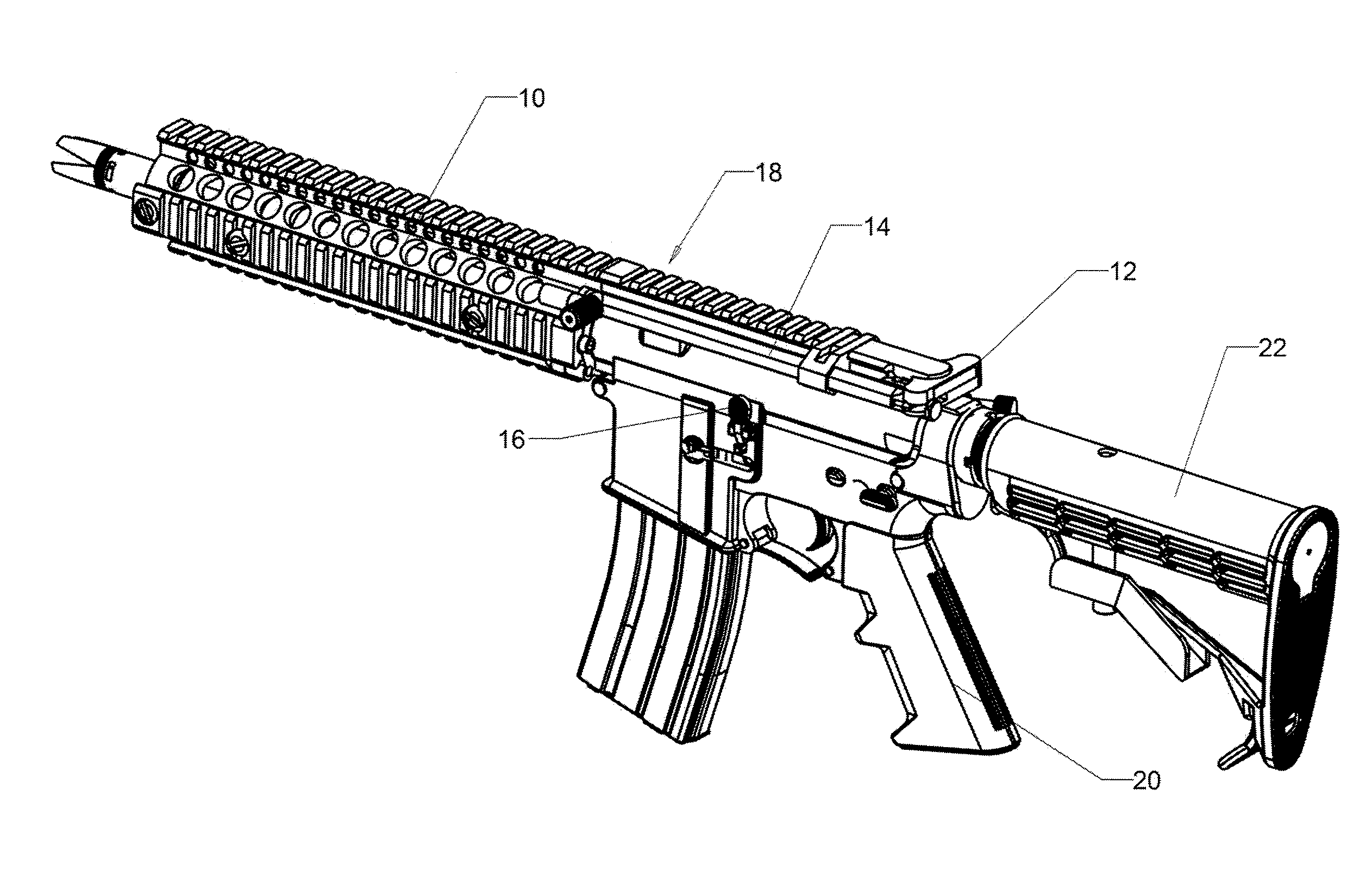
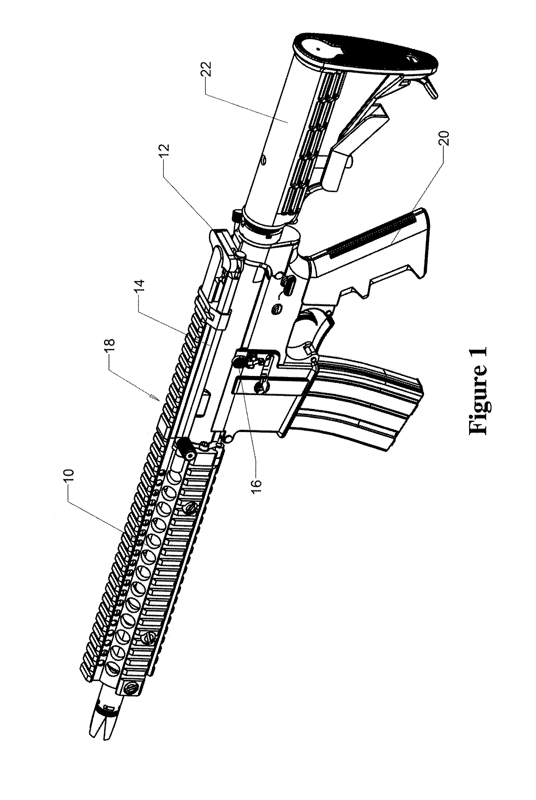
[0036]Referring now to the invention in more detail, FIGS. 1-5 depict one embodiment of the present invention. FIG. 1 shows a firearm with the present invention, the charging handle accessory 14, affixed to the top rail of the firearm 18. The firearm consists of a rear stock 22, a pistol grip 20, a foregrip 10, a bolt catch / release 16, and a charging handle 12.

[0037]For most users, their dominant hand grabs the pistol grip 20 while their non-dominant hand grabs the foregrip 10. The rear stock 22 is designed to be put to the dominant shoulder of the user. When the user operates the charging handle 12, the charging handle 12 travels towards the rear stock 22. The bolt catch / release 16 is located on the left side of the firearm in FIG. 1 and manipulates the locking position of the interior bolt (not shown). The bolt catch / release can also be located on the right side of the firearm.

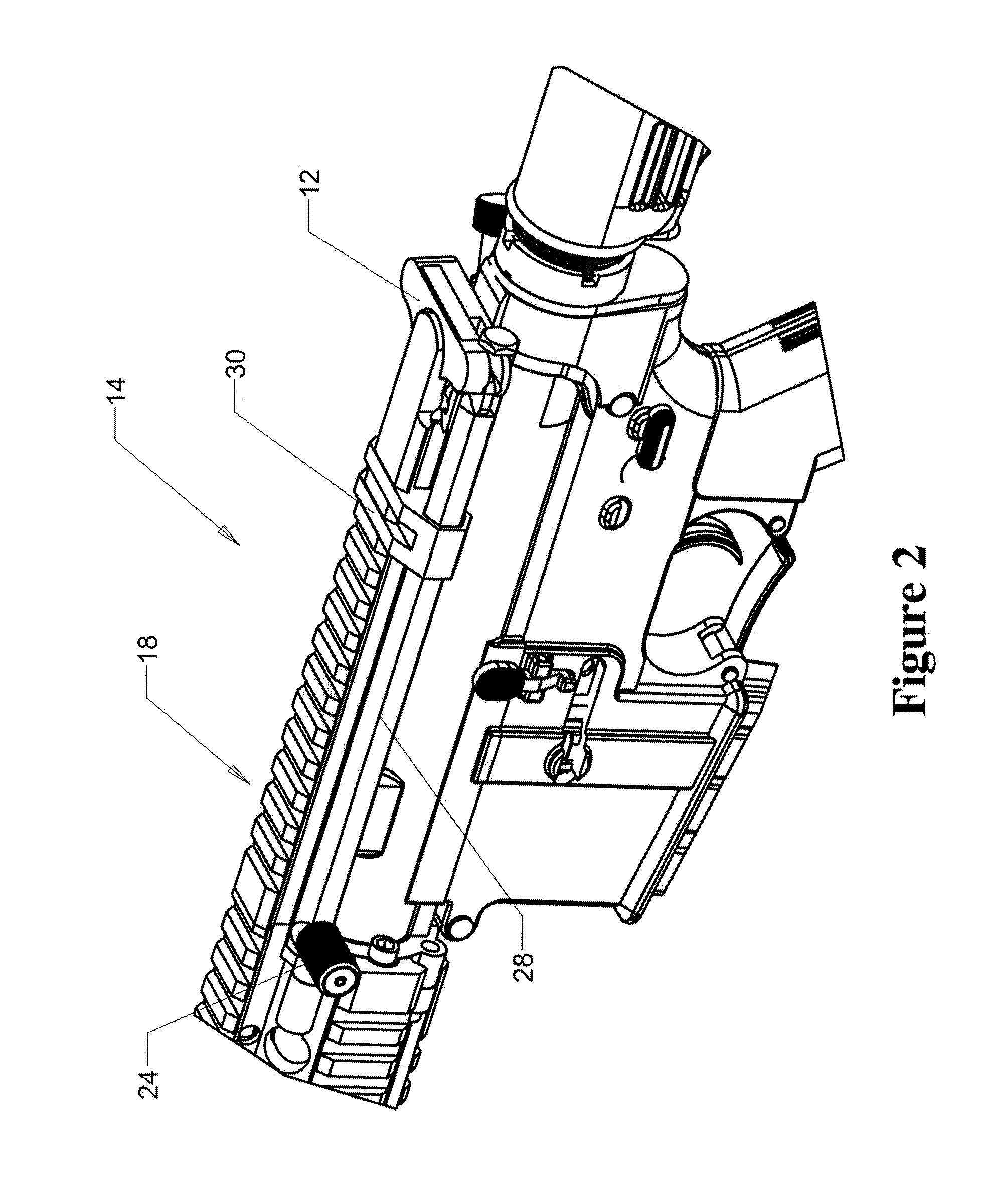
[0038]In FIG. 2 there is shown an enlarged view of the charging handle accessory 14 mounted on the top ra...


PUM


Abstract

An externally mounted firearm accessory and a method of operating the accessory. The firearm accessory includes a mounting clamp and a collar offset extending from the mounting clamp on the side of the firearm on which the bolt catch/release is located, a shaft that is slidably mounted on the collar, a handle at the forward end of the shaft, and a slot at the rear end of the shaft that receives and holds the charging handle of the firearm accessory. The slot is positioned in relation to the charging handle so that, in operation, a user of the firearm accessory pulls rearward on the handle of the shaft of the firearm accessory to push the charging handle rearward and, thereby, depress and open the latch of the charging handle of the firearm. At this point, the user can then push the handle of the firearm accessory forward to pull the charging handle of the firearm into a closed and latched position. A biased spring mechanism associated with the charging handle can also act to push the charging handle forward.

Description

CROSS-REFERENCE TO RELATED APPLICATIONS[0001]This application claims the benefit under 35 U.S.C. §119 of U.S. Provisional Application Ser. No. 62 / 024,498, filed Jul. 15, 2014, which is incorporated by reference herein in its entirety.FIELD OF THE INVENTION[0002]The present invention is in the technical field of firearms. More particularly, the present invention is in the technical field of firearm accessories.BACKGROUND[0003]The invention is designed for use on a gas or piston-operated automatic or semiautomatic firearm such as a carbine, rifle, or pistol so as to relocate operation of the charging handle of a firearm, such as a Colt M4A1 5.56 carbine, M-16, AR-15, or AR-10. It can also be used with other similar firearms.[0004]The charging handle of said firearm comprises a shaft having a forward end portion in the direction of the firearm barrel and a rearward end portion in the direction of the firearm stock. The rearward end portion has a latch engaging the receiver of the firea...

Claims


Application Information

Patent Timeline
Patent Type & Authority Applications(United States)
IPC IPC(8): F41A35/06F41A3/72
CPCF41A3/72F41A35/06
Inventor SWADENER, CHRISTOPHER LUKECOBB, CHADWYCKWALKER, NOAH NATHANIEL
Owner SWADENER CHRISTOPHER LUKE
Why Eureka
Try Eureka