Excitation light source device and optical transmission system

a light source device and light source technology, applied in the field of excitation light source devices and optical transmission systems, can solve the problems of increasing the size and cost of optical amplification devices, affecting the efficiency of optical transmission systems, and the abnormal state of transmission lines cannot be measured, so as to achieve the effect of reducing the intensity of raman excitation ligh

Active Publication Date: 2016-07-28
MITSUBISHI ELECTRIC CORP
View PDF2 Cites 1 Cited by
  • Summary
  • Abstract
  • Description
  • Claims
  • Application Information

AI Technical Summary

Benefits of technology

[0011]The present invention is made to solve problems such as those described above. An object of the invention is to provide an excitation light source device and an optical transmission system that are capable of detecting an abnormal state of a transmission line before the occurrence of damage to the transmission line without an additional device, and reducing the intensity of Raman excitation light when abnormality in the transmission line is detected.
[0015]According to the present invention, since the devices are configured in the above-described manner, an abnormal state of a transmission line can be detected prior to the occurrence of damage to the transmission line without an additional device. Furthermore, when the abnormality in the transmission line is detected, the intensity of Raman excitation light can be reduced.

Problems solved by technology

Thus, it may cause a problem of increasing size and cost of the optical amplification device.
In addition, it may cause another problem that, when the light source for measurement breaks down, an abnormal state of the transmission line cannot be measured.
Hence, there is a problem that, at the time when an abnormal state of the transmission line is detected, an output level may already reach a level where a Raman excitation light source causes damage of the transmission line, and thus, the transmission line has already been damaged.

Method used


Image

  • Excitation light source device and optical transmission system
  • Excitation light source device and optical transmission system
  • Excitation light source device and optical transmission system

Examples


embodiment 1

[0030]In an Embodiment 1, is explained that a system for detecting abnormality in a transmission line based on the state of supply of Raman excitation light (hereinafter, simply referred to as “excitation light”) and the intensity of amplified spontaneous emission noise caused by the excitation light.

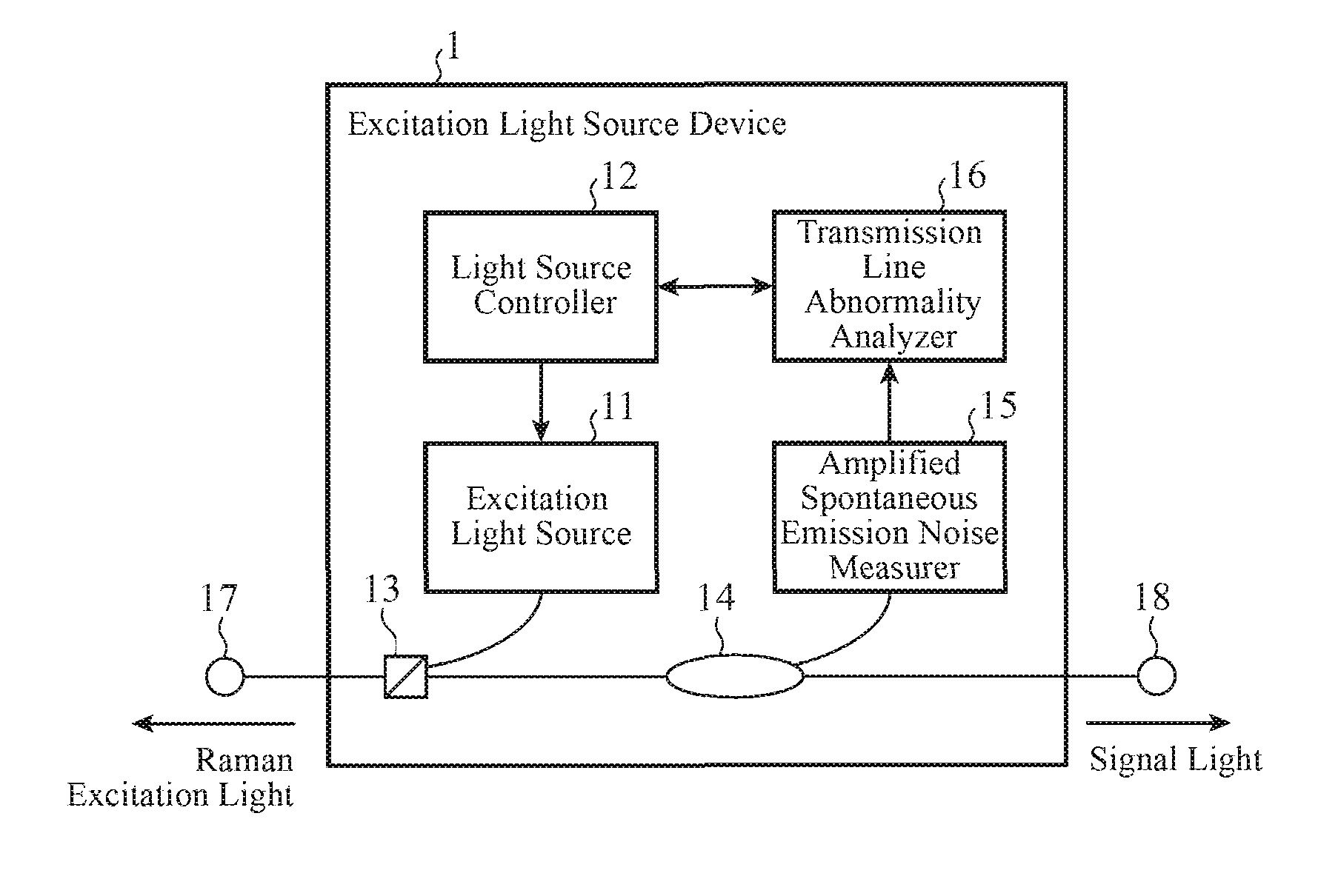
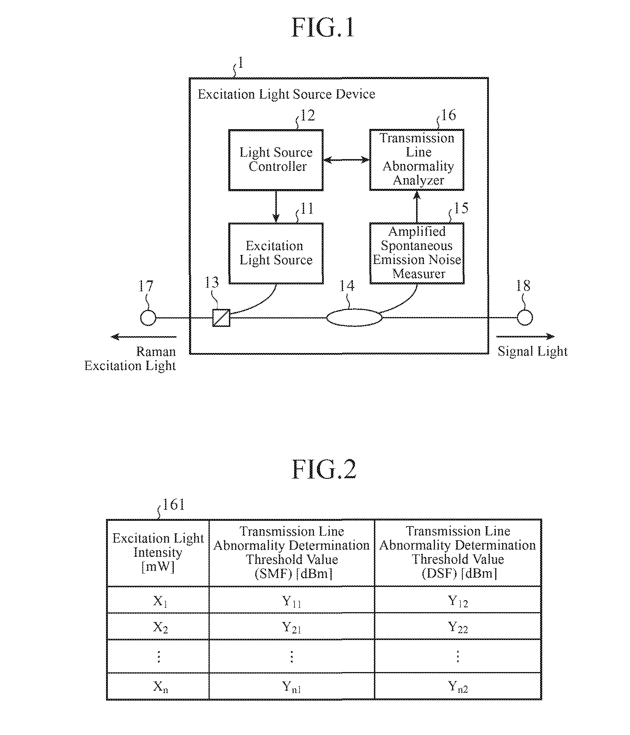
[0031]FIG. 1 is a diagram representing a configuration of an excitation light source device 1 according to the Embodiment 1 of the invention.

[0032]The excitation light source device 1 is to output excitation light that amplifies signal light to a transmission line on which the signal light is transmitted. As shown in FIG. 1, the excitation light source device 1 includes an excitation light source 11, a light source controller 12, a multiplexer 13, a branching device 14, an amplified spontaneous emission noise measurer 15, and a transmission line abnormality analyzer 16.

[0033]Note that the transmission line is implemented by an optical fiber. Signal light (main signal light) flowing thro...

embodiment 2

[0059]In an Embodiment 2, it is explained that a system for detecting abnormality in a transmission line on a bases of the state of supply of excitation light, and Raman gain which is given to signal light and is caused by the excitation light.

[0060]FIG. 6 is a diagram representing a configuration of an excitation light source device 1b according to the Embodiment 2 of the invention. The excitation light source device 1b according to the Embodiment 2 shown in FIG. 6 is configured such that, an amplified spontaneous emission noise measurer 15 of an excitation light source device 1 according to the Embodiment 1 shown in FIG. 1 is removed, and a Raman gain measurer 19 is introduced. Furthermore, a light source controller 12 and a transmission line abnormality analyzer 16 are changed to a light source controller 12b and a transmission line abnormality analyzer 16b, Other configurations are the same and thus are denoted by the same reference signs, and description thereof is omitted.

[006...

embodiment 3

[0080]In an Embodiment 3, it is explained that a system for controlling the intensity of excitation light to obtain Raman gain following a target value, and detecting abnormality in a transmission line based on the intensity of excitation light controlled at that time.

[0081]FIG. 11 is a configuration diagram representing an excitation light source device 1c according to the Embodiment 3 of the invention. The excitation light source device 1c according to the Embodiment 3 shown in FIG. 11 is such that a light source controller 12b and a transmission line abnormality analyzer 16b of an excitation light source device 1b according to the Embodiment 2 shown in FIG. 6 are changed to a light source controller 12c and a transmission line abnormality analyzer 16c. Other configurations are the same and thus are denoted by the same reference signs and description thereof is omitted.

[0082]The light source controller 12c is to control the intensity of excitation light generated by an excitation ...


PUM


Abstract

An excitation light source device includes: an excitation light source to generate the Raman excitation light; a light source controller to control an intensity of the Raman excitation light; an amplified spontaneous emission noise measurer to measure an intensity of amplified spontaneous emission noise caused by the Raman excitation light; and a transmission line abnormality analyzer to detect abnormality in the transmission line on a basis of a control state of the light source controller and a measurement result of the amplified spontaneous emission noise measurer. In a state where the abnormality is not detected, the light source controller controls the intensity of the Raman excitation light to gradually increase to a set value. In a state where the abnormality is detected, the light source controller controls the excitation light source to stop or reduce generation of the Raman excitation light.

Description

TECHNICAL FIELD[0001]The present invention relates to an excitation light source device that outputs Raman excitation light amplifying signal light to a transmission line on which the signal light is transmitted, and also relates to an optical transmission system including the excitation light source device.BACKGROUND ART[0002]In a wavelength division multiplexing optical transmission system that performs long-distance transmission of an optical signal having been subjected to wavelength division multiplexing (WDM), an amplification device that amplifies the optical signal through Raman amplification is introduced. The amplification device amplifies signal light by outputting Raman excitation light with a specific wavelength to a transmission line in order to compensate for a level reduction associated with transmission, and thereby extend relay distance. Note that the level reduction as mentioned herein refers to a reduction in the intensity of signal light according to the transmi...

Claims


Application Information

Patent Timeline
Patent Type & Authority Applications(United States)
IPC IPC(8): H04B10/291H04B10/071H04B10/077
CPCH04B10/2916H04B10/071H04B10/0775G02B6/264H04B10/07H04B10/0791
Inventor IMANISHI, KATSUNORITOKURA, TOSHIYUKISUEOKA, HIDEKITAKATA, KENGO
Owner MITSUBISHI ELECTRIC CORP
Why Eureka
Try Eureka