Guide pad and cutter head for a cutting tool

a cutting tool and cutter head technology, applied in the field of cutting tools, can solve the problems of guide pads subjected to wear and cracks, insufficient cooling/lubrication, and considerable wear and tear of guide pads, and achieve the effect of advantageously low weakening of guide pads

Inactive Publication Date: 2016-08-25
SANDVIK INTELLECTUAL PROPERTY AB
View PDF2 Cites 1 Cited by
  • Summary
  • Abstract
  • Description
  • Claims
  • Application Information

AI Technical Summary

Benefits of technology

[0009]It is an object of the present invention to provide a guide pad for a cutting tool by which it is possible to supply sufficient amounts of cooling and lubricating fluid to a contact zone betwe

Problems solved by technology

During the drilling process, the guide pad is exposed to high temperatures due to friction against the hole wall which, in combination with high pressure against the hole wall, makes the guide pads subjected to wear and formation of cracks.
However, the cooling/lubricating fluid can often not to a sufficient extent reach the entire contact zone between the guide pad and the hole wall, which makes the cooling/lubricating insufficient such that the wearing of and formation of cracks will still be considerable.
A problem with such a des

Method used


Image

  • Guide pad and cutter head for a cutting tool
  • Guide pad and cutter head for a cutting tool
  • Guide pad and cutter head for a cutting tool

Examples


Embodiment Construction

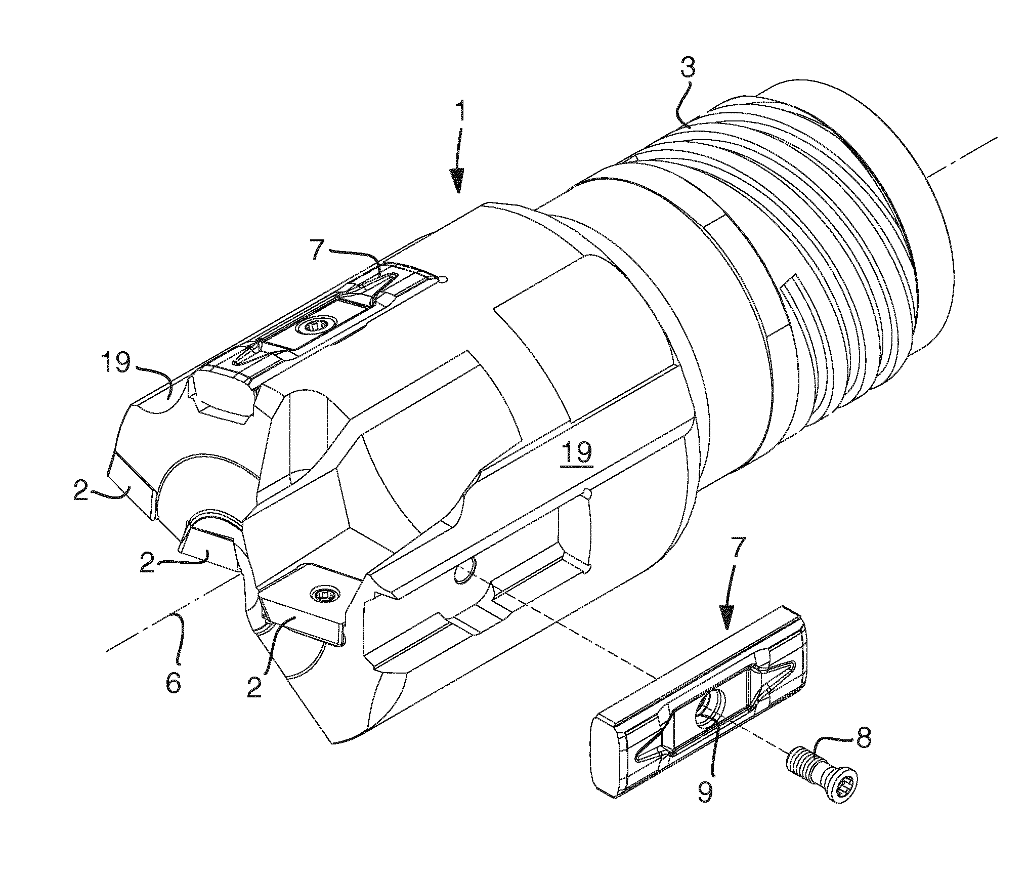
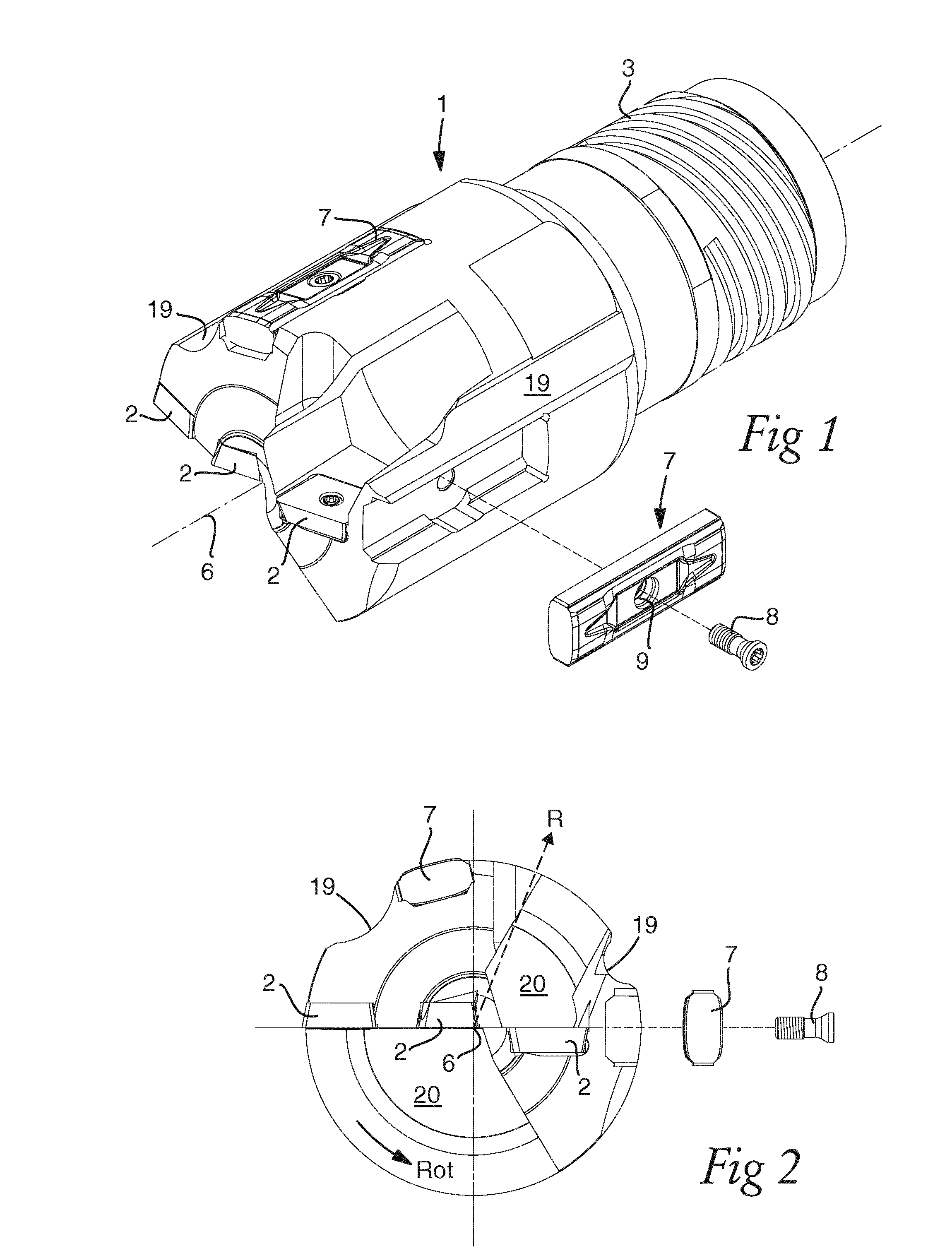
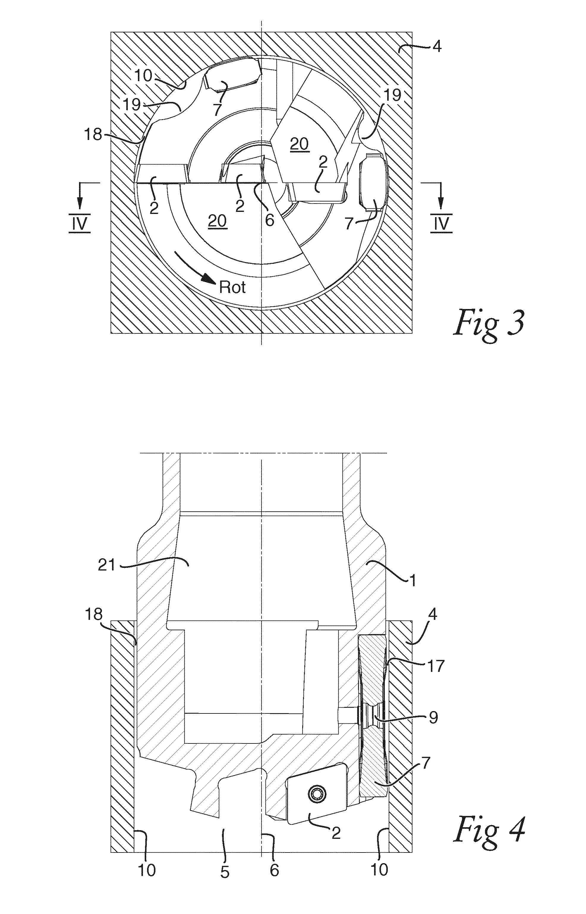
[0029]Reference is first made to FIGS. 1 and 2, which illustrate a cutting tool in form of a cutter head 1 for a drilling tool in a perspective view and a front view, respectively. The cutter head is in a front end provided with cutting inserts 2 and in a rear end with an external thread 3. The cutter head is by means of the external thread adapted to be attached to a not shown drill tube, which can be carried by a suitable supporting device. As is best seen from FIGS. 2 and 3, of which the latter shows a cross section through a work piece 4 and the front end of the cutter head during drilling a hole 5 in the work piece, the cutter head comprises three cutting inserts 2, which are positioned such that their respective cutting edges are positioned along an essentially straight line perpendicular to a rotational axis 6 of the cutter head 1, with two cutting inserts positioned on mainly one side of the rotational axis and one on the other side facing in the opposite direction. During r...


PUM


Abstract

A guide pad for a cutting tool includes a sliding surface, which is convexly curved in a plane perpendicular to a longitudinal axis of the guide pad. A channel-shaped recess is formed in the sliding surface that extends in the direction of the longitudinal axis of the guide pad and terminates before reaching an end of the sliding surface at an end of the guide pad.

Description

[0001]The present invention relates to a guide pad for a cutting tool, the guide pad comprising a sliding surface, which is convexly curved as viewed in a plane perpendicular to a longitudinal axis of the guide pad.[0002]The invention also relates to a cutter head comprising such a guide pad.BACKGROUND OF THE INVENTION[0003]Guide pads are used during cutting machining in metals and other hard materials on e.g. cutter heads of deep hole drilling tools in order to prevent wear of the cutter head and to guide the drilling tool during the drilling process and thereby maintain the cutter head on a straight axis line to create a bore hole which is straight with an as high accuracy as possible. For this purpose at least two guide pads are mounted in a respective seating on an outer periphery or envelope surface of the cutter head by means of e.g. screwing, clamping or soldering. A sliding surface of the guide pad which is facing outwards and bears against the circumferential hole wall of t...

Claims


Application Information

Patent Timeline
IPC IPC(8): B23B51/04
CPCB23B51/0493B23B2250/12B23B2251/56
Inventor HANSSON, PER
Owner SANDVIK INTELLECTUAL PROPERTY AB
Why Eureka
Try Eureka