Dimming circuit for LED

Active Publication Date: 2016-12-22
TCL CHINA STAR OPTOELECTRONICS TECH CO LTD
View PDF3 Cites 3 Cited by
  • Summary
  • Abstract
  • Description
  • Claims
  • Application Information

AI Technical Summary

Benefits of technology

The LED dimming circuit of this patent text is designed to control multiple LED strings in a controllable backlight module to light up at different moments in a cycle. The circuit has a constant output power without any instability. The delay circuit controls sequentially the PWM dimming signal, resulting in a stepped delay PWM dimming signal. This causes the LEDs to turn on successively, resulting in a uniform distribution of lighting time and constant outputting power. Compared to prior art, the LED dimming circuit avoids circuit instability and ensures a constant outputting power.

Problems solved by technology

In each working cycle, because of the large output power range, the current of the inductors may change frequently between the maximum and minimum values, which generates noise, impacts the components of the circuit, and results to a big wave of output voltage, so the circuit is unstable.

Method used


Image

  • Dimming circuit for LED
  • Dimming circuit for LED
  • Dimming circuit for LED

Examples


Embodiment Construction

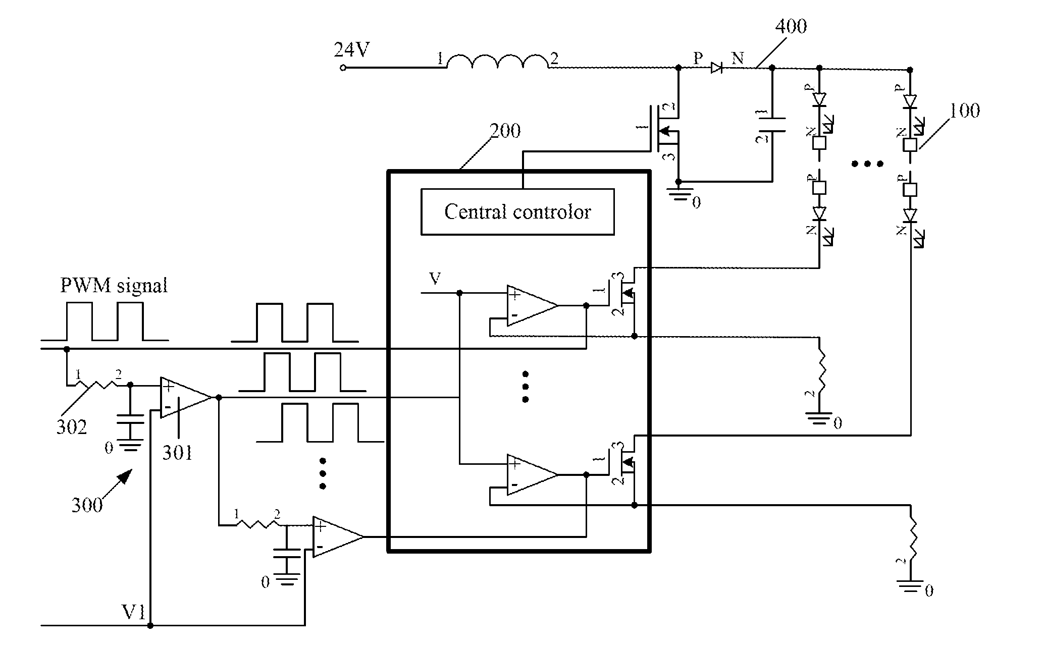
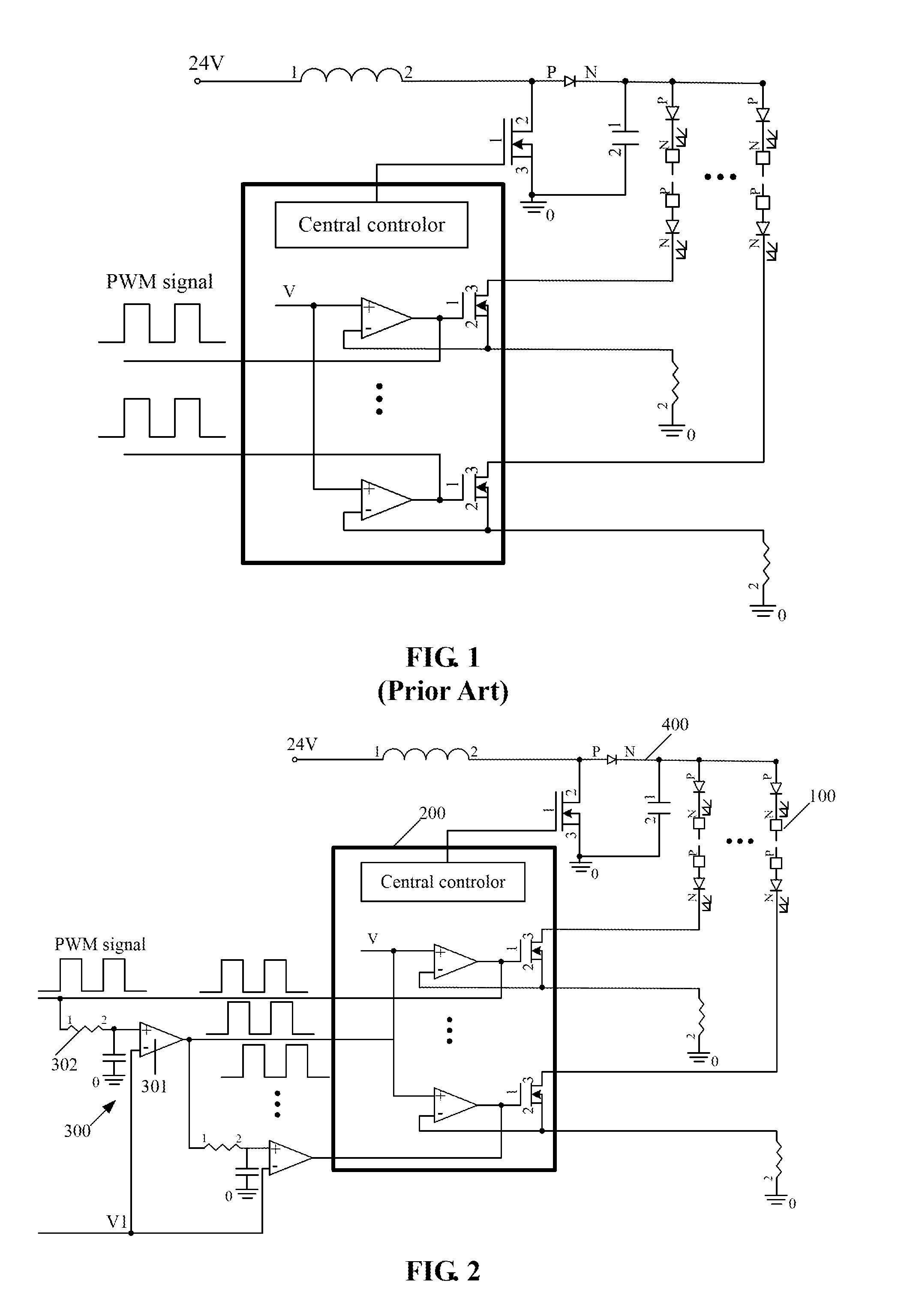
[0019]Please refer to FIG. 1, the present invention provides a dimming circuit for LEDs, configured to control a plurality of LED strings 100 to light up at different moment in a working cycle, the circuit includes:

[0020]several sets of LED string 100 connected in parallel respectively;

[0021]driving circuit 200 coupled to the LED strings 100 to drive them to light up;

[0022]control circuit 300 coupled to the driving circuit 200 to control the LED series 100 to light up by inputting the pulse width modulated signal (PWM dimming signal) to the driving circuit 200;

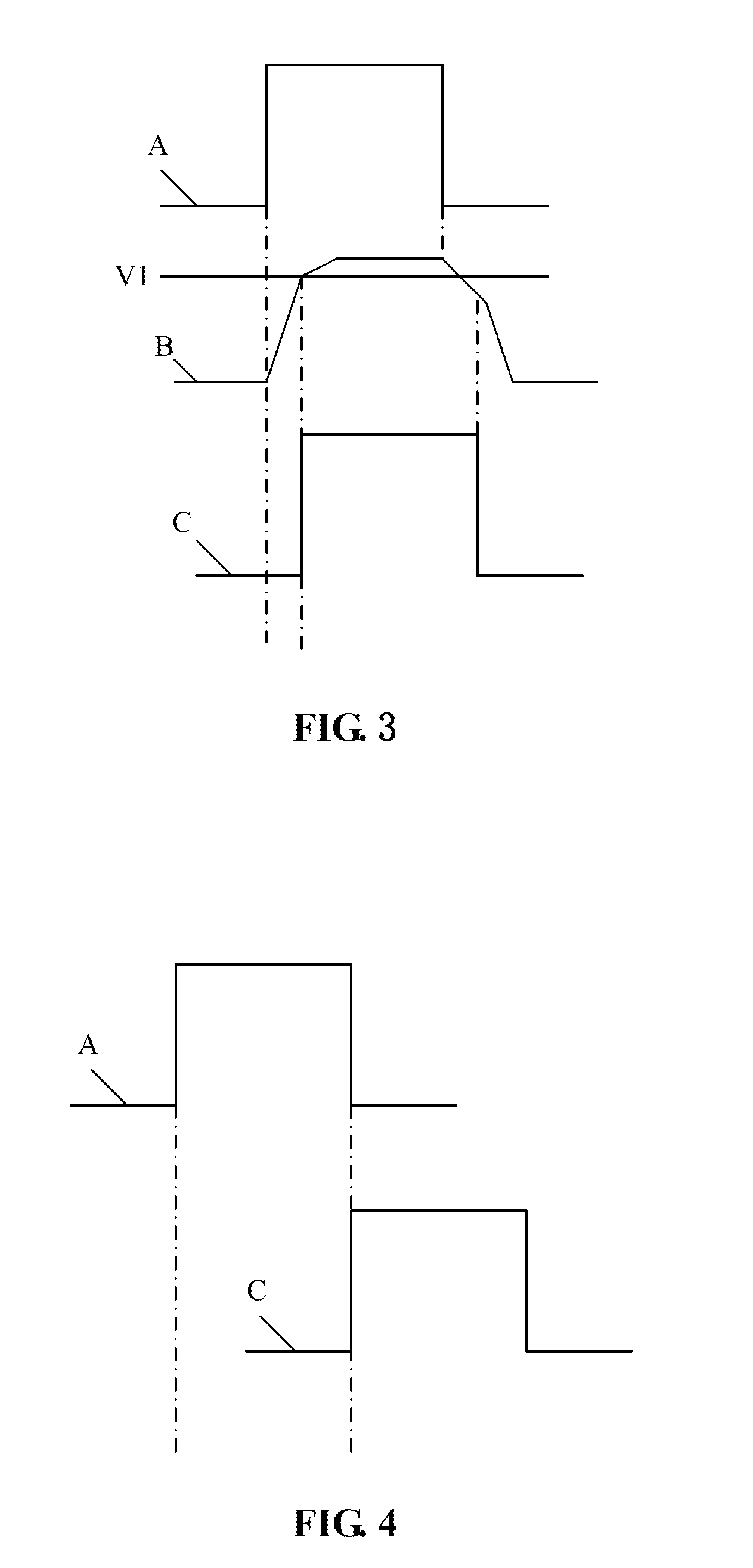
[0023]The control circuit 300 includes a voltage comparator 301 and a delay circuit 302. The voltage comparator 301 is coupled between the delay circuit 302 and the driving circuit 200, each delay circuit 302 and each driving circuit 200 are connected in series. The delay circuit 302 converts the PWM dimming signal to a delay signal, and then the voltage comparator 301 converts the sine wave signal of the delay signal to a squ...


PUM


Abstract

A LED dimming circuit, configured to control a plurality of LED strings to light up at different moment in a cycle, the circuit includes several sets of LED strings connected in parallel respectively; driving circuits coupled to the LED strings and driving them to light up; control circuits coupled to the driving circuits to control the LED series to light up by inputting pulse width modulated signals to the driving circuits; the control circuit includes a voltage comparator and a delay circuit, the voltage comparator is coupled between the delay circuit and the driving circuit, each delay circuit and each driving circuit are connected in series thereof, the delay circuit converts the pulse width modulated signal to a delay signal, the voltage comparator converts the sine wave signal to a square wave or a rectangular wave signal.

Description

FIELD OF THE INVENTION[0001]The present invention relates to driving circuits of backlight modules, and more particularly to dimming circuits for light emitting diode (“LED”).BACKGROUND OF THE INVENTION[0002]Please refer to FIG. 1, which is a circuit diagram of a backlight driving circuit for LEDs according to a prior art, and the light adjustment thereof is controlled by a pulse width modulated signal (PWM dimming signal). When the voltage of the PWM dimming signal has a constant DC high level, the MOS tubes, conducted with a constant current of the LEDs and connected in series with the LEDs in the IC, is always in the conducting state, the current of the LEDs is constant, then their brightness is the highest. When to dimmer, because the PWM dimming signal has a rectangular wave, the MOS tubes in the IC switches between on and off, the LED's current has also a rectangular wave, and because the average value of the LED's current declines, the brightness is reduced.[0003]During the d...

Claims


Application Information

Patent Timeline
IPC IPC(8): H05B37/02H05B33/08H05B44/00
CPCH05B37/0281H05B33/0827H05B33/0845G09G3/3426G09G2310/024G09G2320/064H05B45/395H05B45/46H05B45/38H05B45/30H05B45/10H05B45/325H05B47/16Y02B20/30
Inventor ZHANG, HUA
Owner TCL CHINA STAR OPTOELECTRONICS TECH CO LTD
Why Eureka
Try Eureka