
Image stabilization apparatus, method for controlling the same, and storage medium
- Summary
- Abstract
- Description
- Claims
- Application Information
AI Technical Summary
Benefits of technology
Problems solved by technology
Method used
Image

Examples
first embodiment
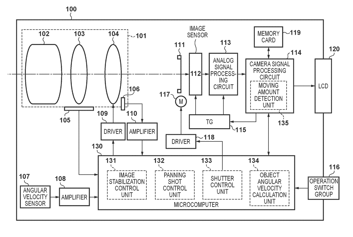
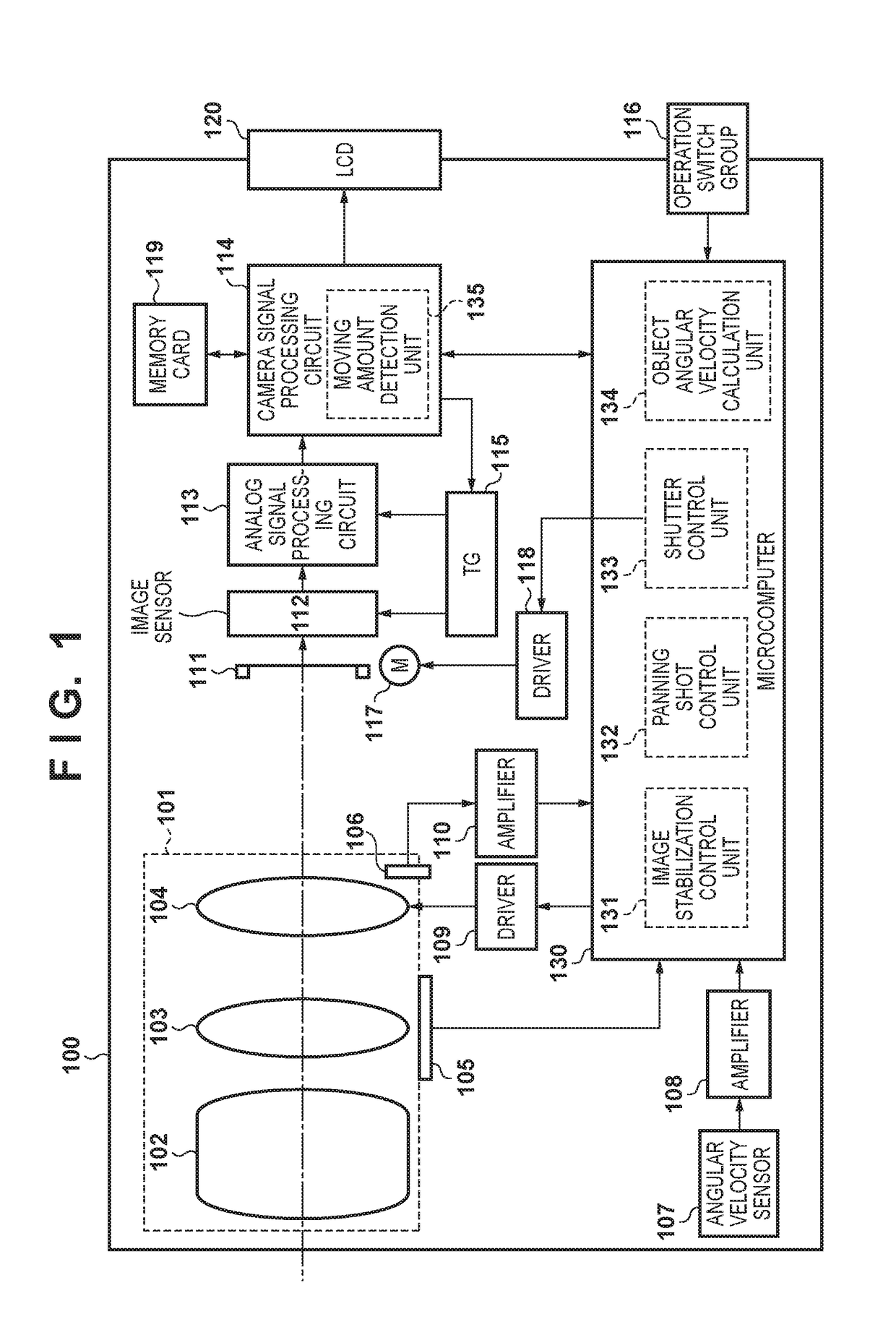
[0030]FIG. 1 is a block diagram showing a configuration of a camera that is an image capturing apparatus according to a first embodiment in which an image stabilization apparatus according to the present invention is mounted. In FIG. 1, in a camera 100, a lens is integrated in the body of the camera. However, the present invention is not limited to a camera in which a lens and the body of the camera are integrally configured, and is also applicable to a single-lens reflex camera configured such that a lens is detachably attached to the body of the camera.
[0031]The camera 100 includes a capturing lens unit 101 including a main capturing optical system 102, a zoom lens group 103 capable of changing the focal distance, and a shift lens group 104 that optically corrects an image blur with respect to the optical axis caused by camera vibration by moving in a direction perpendicular to the optical axis. The capturing lens unit 101 forms an object image on an image sensor 112, which will b...
second embodiment
[0064]Hereinafter, an image capturing apparatus according to a second embodiment of the present invention will be described. FIG. 14 is a diagram showing accumulated information generated by an object angular velocity calculation unit 134 according to the second embodiment. In the second embodiment, the operation of the object angular velocity calculation unit 134 is different from that of the first embodiment. In the first embodiment, in S1504, the angular velocity is held for each frame, and only the most recent coordinates are held, whereas in the second embodiment, both the angular velocity and the coordinates are held for each frame.
[0065]FIG. 15 is a flowchart illustrating an operation performed by a moving amount detection unit 135 according to the second embodiment. A difference from the operation of the first embodiment is that the processing of S110 is added between steps S107 and S108. After information has been transmitted to the object angular velocity calculation unit ...
PUM
 Abstract
Description
Claims
Application Information