Control apparatus for correcting blur, lens apparatus, imaging apparatus, control method, and storage medium
a control apparatus and blur correction technology, applied in the field of control apparatus, can solve the problems of difficult to accurately detect background motion vectors and inability to perform highly accurate image stabilization, and achieve the effect of high-accuracy image stabilization
- Summary
- Abstract
- Description
- Claims
- Application Information
AI Technical Summary
Benefits of technology
Problems solved by technology
Method used
Image
Examples
first embodiment
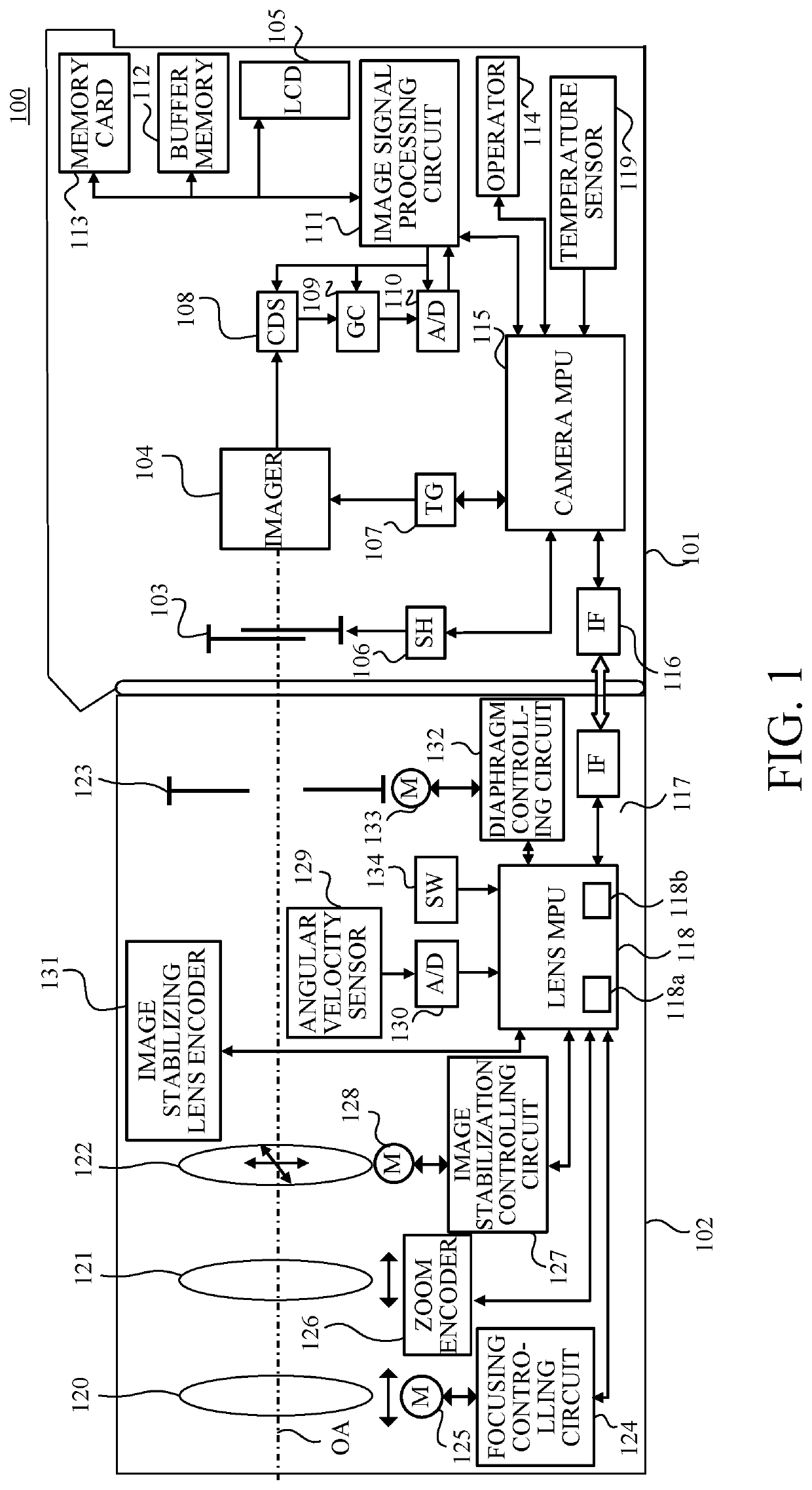
[0017]Firstly, a description will be given of a configuration of a camera system (imaging system) in this embodiment with reference to FIG. 1. A camera system (imaging system) 100 includes a camera body (imaging apparatus) 101 and an interchangeable lens (lens apparatus) 102 detachably attachable to and communicable with the camera body 101.
[0018]Before an imaging operation (image capturing operation) (during so-called aiming), a focal plane shutter 103 is opened, and an imaging light beam (image capturing light beam) from an object passes through an imaging optical system of the interchangeable lens 102 and forms an image on an imager (imaging unit) (image sensor) 104. An LCD 105 displays the image formed on the imager 104. Thereby, a user can view the object image during the aiming. The imager 104 is a CMOS sensor, and photoelectrically converts the object image (optical image) formed via the imaging optical system.
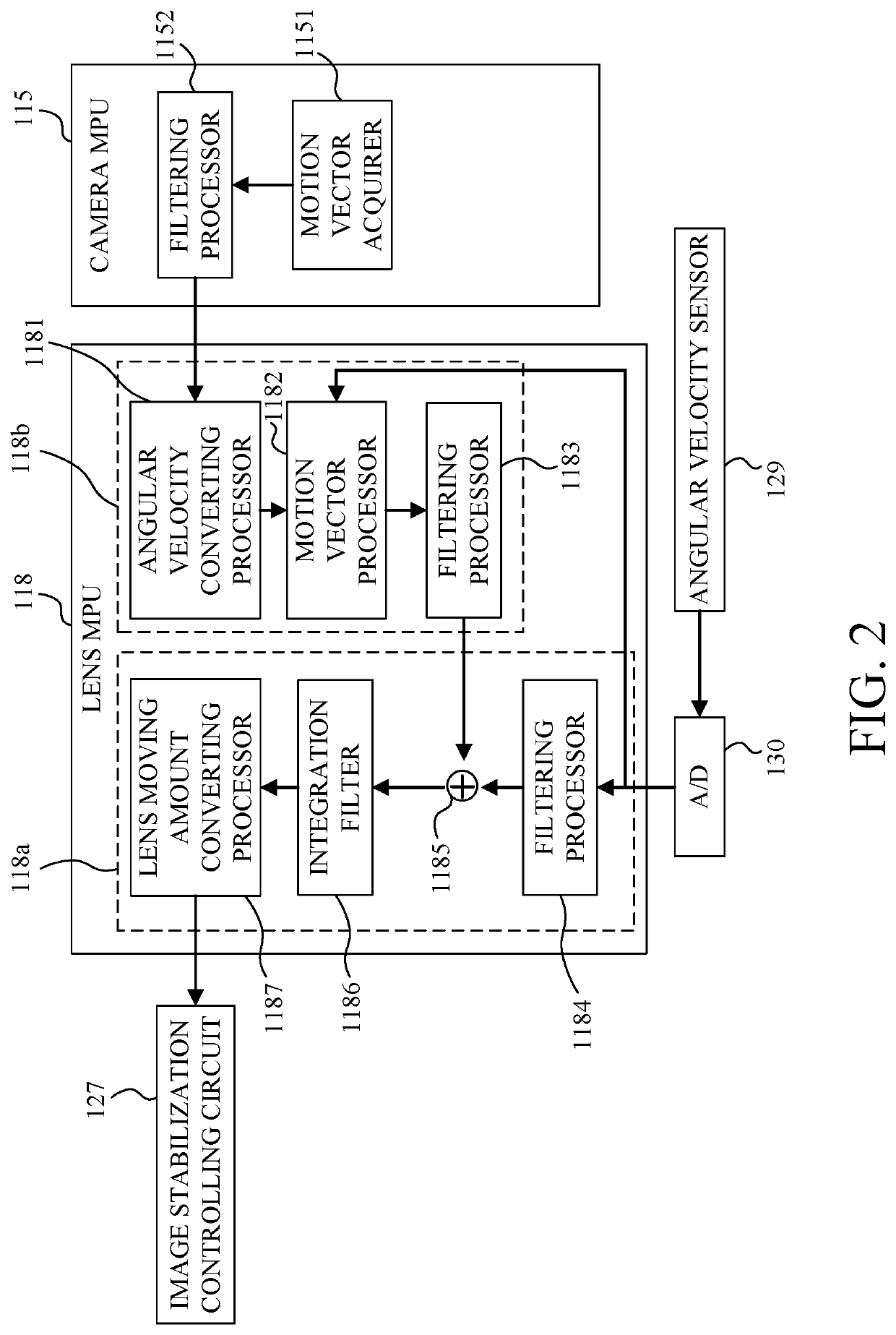
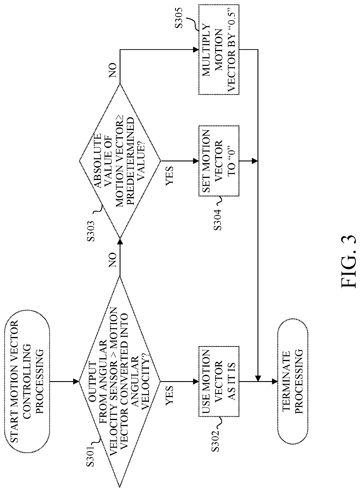
[0019]When an imaging operation starts (an operation for starting ...
second embodiment
[0041]Next, a description will be given of the second embodiment of the present invention with reference to FIGS. 4 and 5. This embodiment basically has the same configuration of the camera system as the configuration described with reference to FIG. 1, and thus a description thereof will be omitted.
[0042]With reference to FIG. 4, a flow will be described from when the camera MPU 115 acquires the motion vector to when the signal becomes the lens target signal for inputting to the image stabilization controlling circuit 127 of the interchangeable lens 102 in this embodiment. FIG. 4 is a block diagram illustrating the control apparatus.
[0043]The feedback controller 118b includes an angular velocity converting processor 1181, a filtering processor 1188, and a motion vector processor (second acquirer) (motion vector feedback amount controlling processor) 1189. The angular velocity converting processor 1181 is configured to convert the input motion vector information (image plane moving ...
PUM
 Abstract
Description
Claims
Application Information
 - R&D
- Intellectual Property
- Life Sciences
- Materials
- Tech Scout
- Unparalleled Data Quality
- Higher Quality Content
- 60% Fewer Hallucinations
Browse by: Latest US Patents, China's latest patents, Technical Efficacy Thesaurus, Application Domain, Technology Topic, Popular Technical Reports.
© 2025 PatSnap. All rights reserved.Legal|Privacy policy|Modern Slavery Act Transparency Statement|Sitemap|About US| Contact US: help@patsnap.com


