Image stabilization apparatus and image pickup apparatus

a technology of image stabilization and image plane, which is applied in the direction of television systems, instruments, printing, etc., can solve the problems of large calculation amount for obtaining the blur amount in the image plane, inability to ignore the influence of parallel movement, and large shooting magnification, so as to achieve accurate image stabilization and reduce calculation amount

Inactive Publication Date: 2012-12-25
CANON KK
View PDF6 Cites 1 Cited by
  • Summary
  • Abstract
  • Description
  • Claims
  • Application Information

AI Technical Summary

Benefits of technology

[0017]The present invention is made in view of the aforementioned problems, and has an object to provide an image stabilization apparatus and an image pickup apparatus which enable accurate image stabilization without a control failure, reduces a calculation amount, and enable image stabilization calculation corresponding to a change of a principal point position of a shooting optical system, in whatever state an angular blur and a parallel blur may coexist.

Problems solved by technology

However, when close-up shooting is performed for shooting a flower or the like, the shooting magnification is very large, and the influence of parallel movement cannot be ignored.
H07-225405 has the problem that the calculation amount for obtaining the blur amount in the image plane becomes tremendous, and the algorithm of calculation becomes very complicated.
Further, the fact that the rotation center position n is ∞ means that the movement due to the angle in the pitching direction or in the yawing direction is absent, and this movement cannot be detected by the angular velocity sensor.
The correction amount can be calculated by using the output of the two acceleration sensors, but the precision is low and the calculation amount becomes tremendous.
Further, by the mathematical expression in this case, the correction calculation of the movement in the optical axis direction cannot be made.

Method used


Image

  • Image stabilization apparatus and image pickup apparatus
  • Image stabilization apparatus and image pickup apparatus
  • Image stabilization apparatus and image pickup apparatus

Examples


embodiment 1

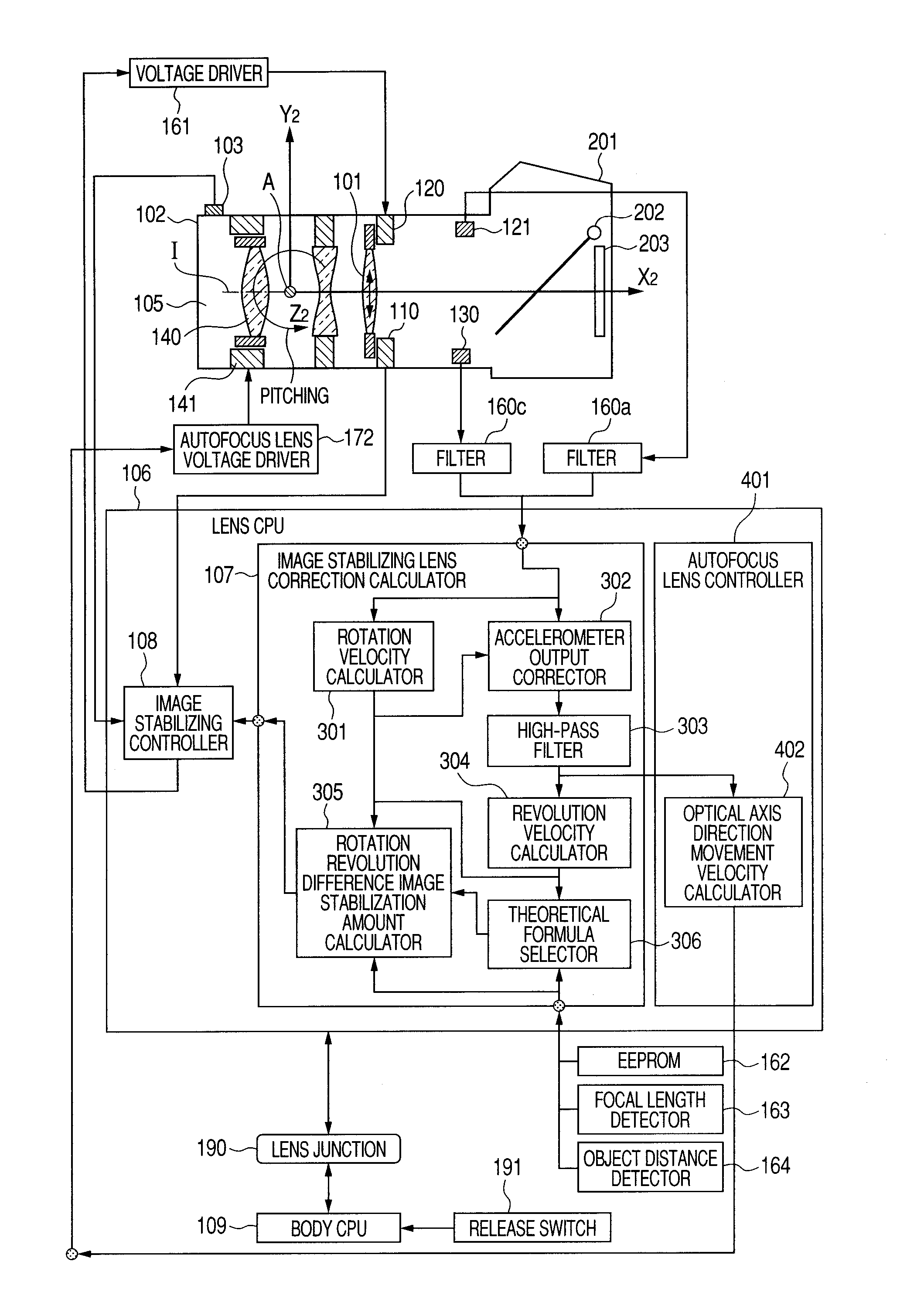
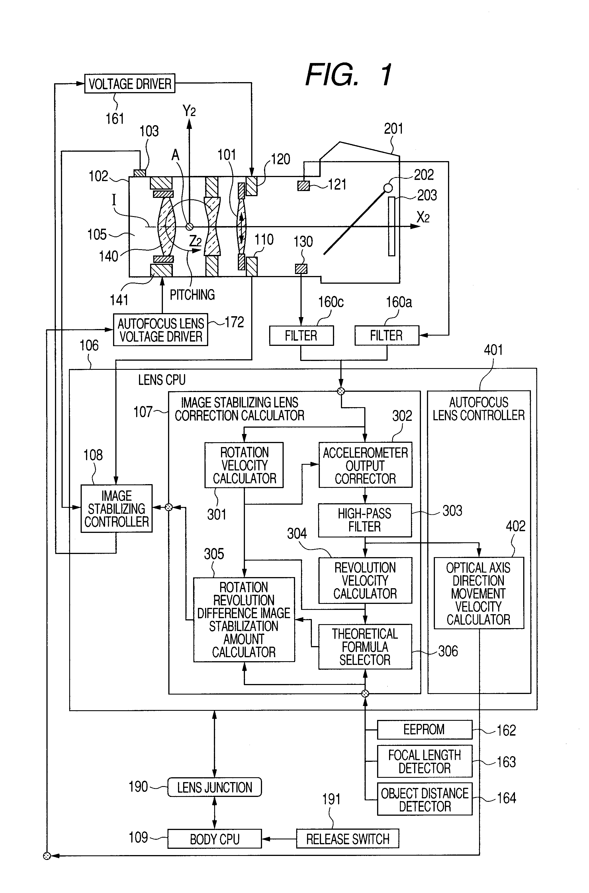
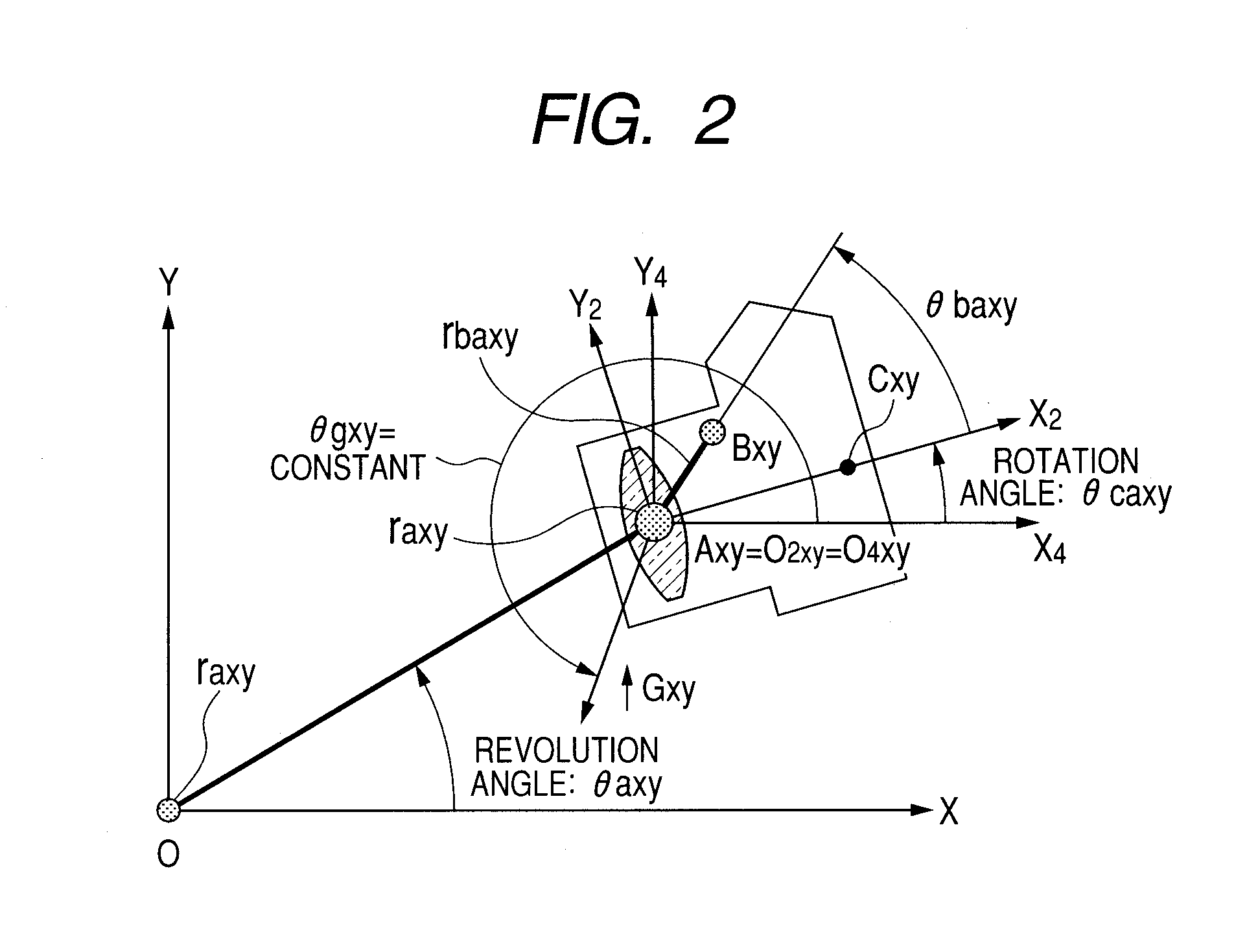
[0045]In the following embodiment, the shake movement of the camera held by human hands, and an image movement which occurs on an image plane as a result of the shake movement of the camera will be expressed by “rotation revolution movement expression” with the movement model expressing a rotation movement and a revolution movement and a geometrical-optical expression being combined.

[0046]The present embodiment is an image stabilization apparatus which calculates a camera movement from the measured values of an accelerometer and an angular velocity sensor, and the rotation revolution movement expression, and further calculates an image movement. By performing drive control of a part of the shooting lens or a part or whole of the image pickup device based on a calculated value of the image movement, the image blur is corrected. Alternatively, the present invention provides an image stabilization apparatus which corrects an image blur by performing image processing of a shot image bas...

embodiment 2

[0227]By using FIGS. 17A and 17B, embodiment 2 will be described. The same flow as in FIGS. 3A and 3B according to embodiment 1 is included. Therefore, the same reference numerals and characters are used for the same flow, and the description will be omitted.

[0228]After revolution angular velocity calculation of S1100 in FIGS. 17A and 17B, the flow proceeds to S2610. In S2610, it is determined whether the imaging magnification of shooting is 0.2 or more (predetermined value or more). In the case of the imaging magnification being 0.2 or more, the flow proceeds to S2620, and in the case of the imaging magnification being less than 0.2 (less than the predetermined value), the flow proceeds to S1130. In S1130, rotation movement correction calculation is performed as in embodiment 1.

[0229]In S2620, it is determined whether or not the revolution angular velocity with respect to the rotation angular velocity is between −0.9 and +0.9 (within ranges between predetermined values). If it is w...


PUM


Abstract

An image stabilization apparatus has an angular velocity detector detecting an angular velocity applied thereto and outputting the angular velocity, an acceleration detector detecting an acceleration applied to the image stabilization apparatus and outputting the acceleration, a principal point calculation unit calculating a principal point position of a shooting optical system, an rotation angular velocity calculation unit calculating a rotation angular velocity component about the principal point of the shooting optical system based on an output of the angular velocity detector, a revolution angular velocity calculation unit calculating a revolution angular velocity component about an object based on the output of the acceleration detector and a calculation result of the rotation angular velocity calculation unit and correcting the calculated revolution angular velocity component according to the principal point position, and a controlling unit performing image stabilization control based on a difference between the rotation and corrected revolution angular velocity components.

Description

BACKGROUND OF THE INVENTION[0001]1. Field of the Invention[0002]The present invention relates to an image stabilization apparatus which prevents deterioration of a shot image by correcting an image blur due to shake, and an image pickup apparatus including the image stabilization apparatus.[0003]2. Description of the Related Art[0004]FIG. 18 is a view showing an outline of an image stabilization apparatus included in the conventional camera. A shake which occurs to the camera has six degrees of freedom in total, which are rotational movements of three degrees of freedom constituted of pitching, yawing and rolling movement, and translation movements of three degrees of freedom constituted of movements in an X-axis, a Y-axis and a Z-axis directions. The image stabilization apparatuses which are commercialized at present usually corrects the image blur due to the rotational movements of two degrees of freedom constituted of pitching and yawing movements which significantly influence im...

Claims


Application Information

Patent Timeline
Patent Type & Authority Patents(United States)
IPC IPC(8): H04N5/228
CPCG03B5/00H04N5/23248H04N5/23258G03B2205/0007G03B2217/005H04N23/68H04N23/6812
Inventor NOTO, GOROMASUDA, SHINICHI
Owner CANON KK
Why Eureka
Try Eureka