
Lens apparatus, image pickup system, control method of lens apparatus, and storage medium

a control method and lens technology, applied in the field of lenses, can solve the problems that the image stabilizing function of interchangeable lenses cannot be effectively utilized, and provide a proper image stabilization

Active Publication Date: 2022-08-18
CANON KK
View PDF2 Cites 0 Cited by
  • Summary
  • Abstract
  • Description
  • Claims
  • Application Information

AI Technical Summary

Benefits of technology

The present invention offers a lens system, a camera system, a method to control the lens system, and a storage medium that can effectively stabilize images even if the camera body does not have a translational image-stabilizing function.

Problems solved by technology

Therefore, the image stabilizing function of the interchangeable lens cannot be effectively utilized.
The method disclosed in JP 2007-33740 cannot provide a proper image stabilization when an interchangeable lens having no translational image-stabilizing function is attached to a camera body having no translational image-stabilizing function, because the influence of the translational shake cannot be removed.

Method used


Image

  • Lens apparatus, image pickup system, control method of lens apparatus, and storage medium
  • Lens apparatus, image pickup system, control method of lens apparatus, and storage medium
  • Lens apparatus, image pickup system, control method of lens apparatus, and storage medium

Examples


first embodiment

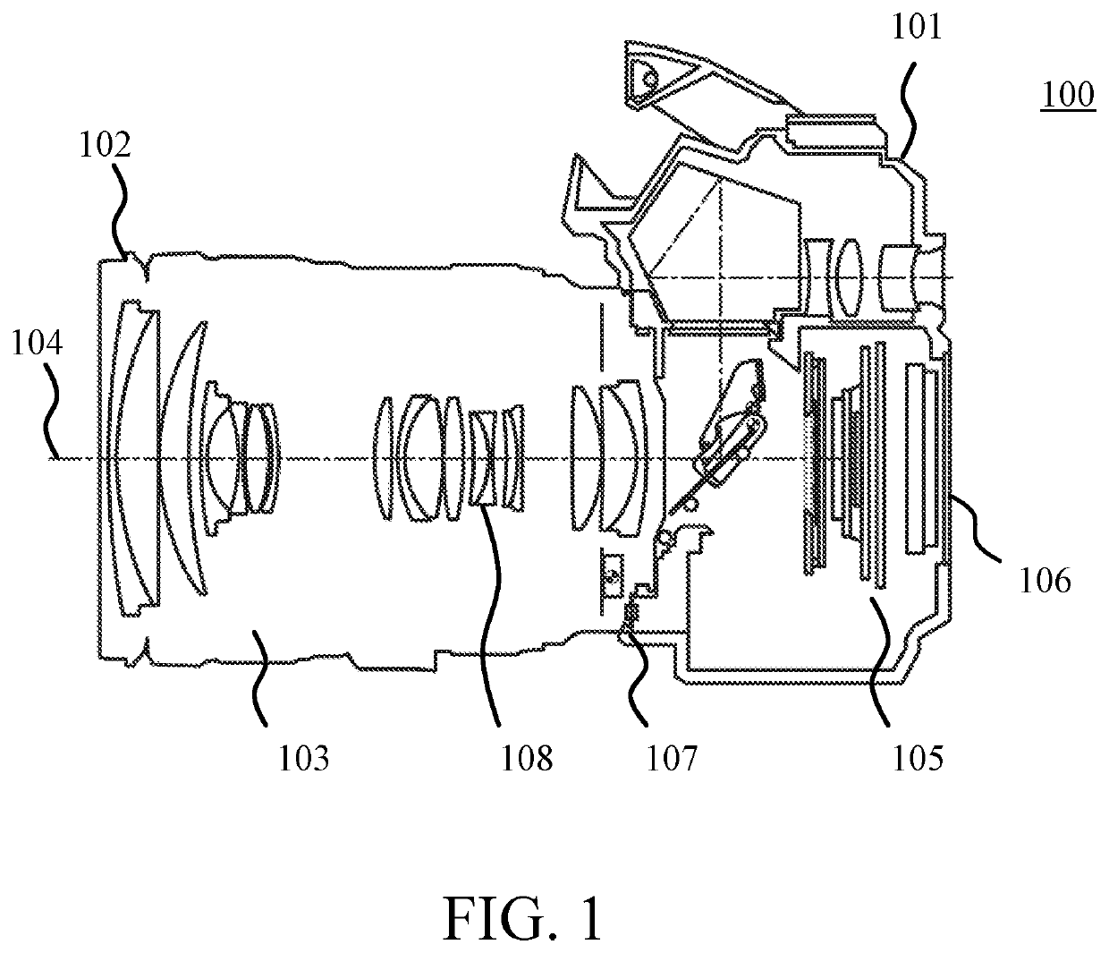
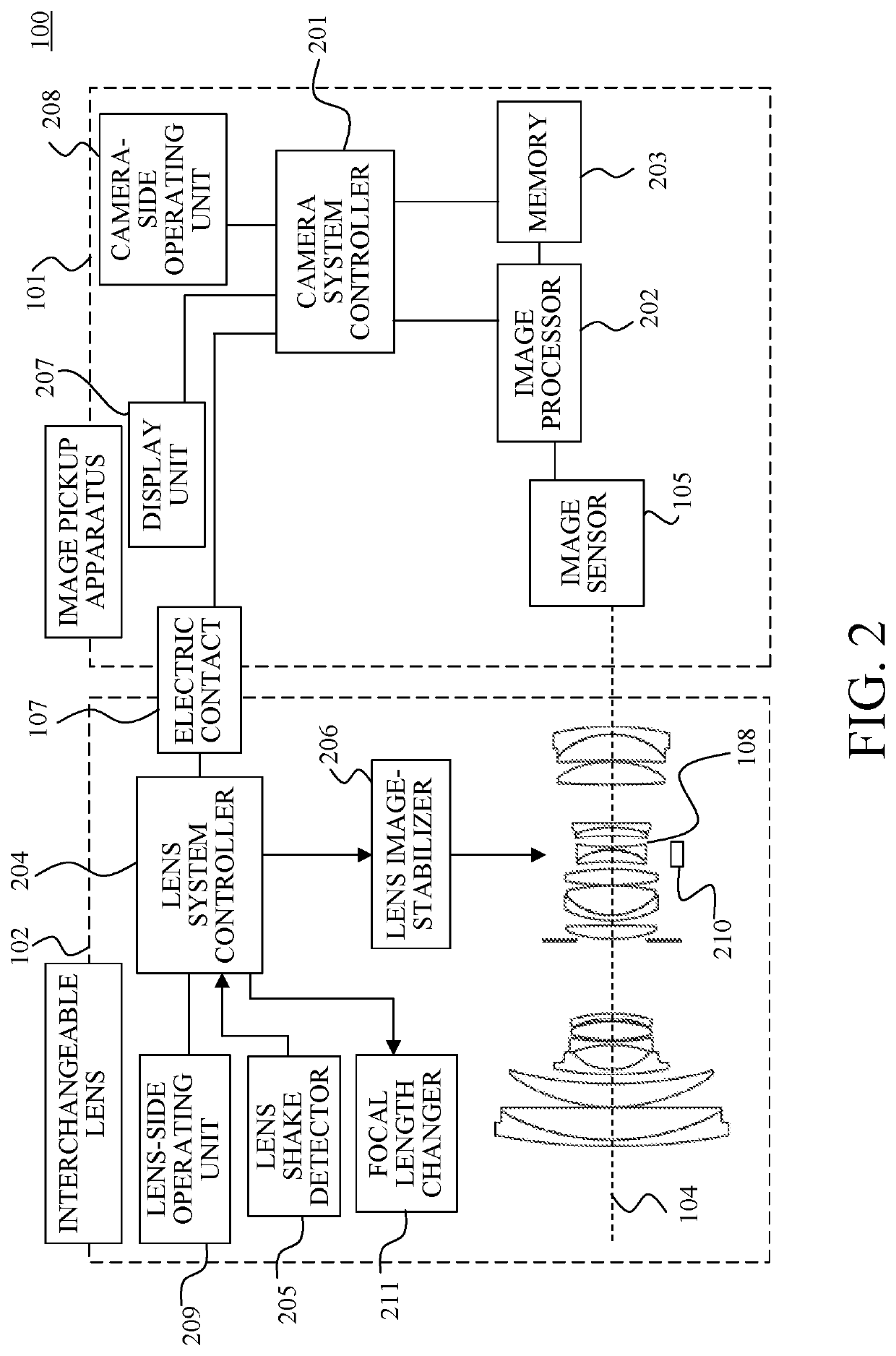
[0018]Referring now to FIGS. 1 to 7, a description will be given of an image pickup system (camera system) 100 according to a first embodiment of the present invention. FIG. 1 illustrates a central section of the image pickup system 100. The image pickup system 100 includes an image pickup apparatus (camera body) 101, and an interchangeable lens (lens apparatus) 102 attachable to and detachable from the image pickup apparatus 101. Reference numeral 103 denotes an imaging optical system including a plurality of lenses. Reference numeral 104 denotes an optical axis of the imaging optical system 103. Reference numeral 105 denotes an image sensor (image pickup element). Reference numeral 106 denotes a rear display unit. Reference numeral 107 denotes an electrical contact between the image pickup apparatus 101 and the interchangeable lens 102. Reference numeral 108 denotes an image-stabilizing lens unit (image stabilizer) provided to an interchangeable lens 102.

[0019]FIG. 2 is a block di...

second embodiment

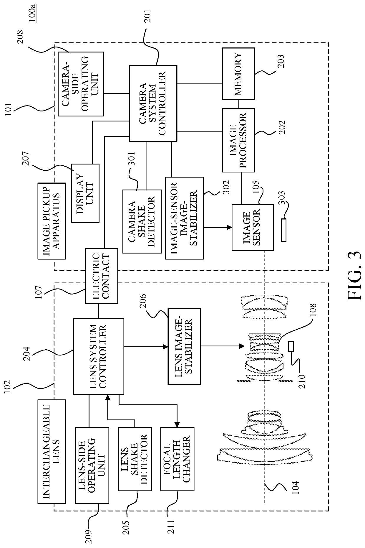
[0046]Referring now to FIGS. 8 and 9, a description will be given of an image pickup system according to a second embodiment of the present invention. When the interchangeable lens 102 has a translational image-stabilizing function, the first embodiment provides the image stabilization in which the lens image-stabilizer 206 provides the angular image stabilization and the image-sensor image-stabilizer 302 provides the translational image stabilization. On the other hand, in this embodiment, the angular image stabilization is made by both the lens image-stabilizer 206 and the image-sensor image-stabilizer 302. A description will now be given of only differences from the first embodiment.

[0047]In this embodiment, both the lens image-stabilizer 206 and the image-sensor image-stabilizer 302 simultaneously provide the angle image stabilizations based on the shake information of both the lens shake detector 205 and the camera shake detector 301. If the lens-side shake detector and the cam...


PUM


Abstract

A lens apparatus attachable to and detachable from an image pickup apparatus includes a detector configured to detect an angular shake of the lens apparatus, an image stabilizer configured to provide an image stabilization by driving part of an imaging optical system in the lens apparatus, and a controller configured to calculate a driving amount using a rotation angle based on an output of the detector and information for converting the rotation angle into the driving amount. The controller changes the information based on the image pickup apparatus attached to the lens apparatus.

Description

BACKGROUND OF THE INVENTIONField of the Invention[0001]The present invention relates to a lens apparatus having an image stabilizing apparatus.Description of the Related Art[0002]There have conventionally been known an image pickup apparatus (camera body) and a lens apparatus (interchangeable lens) each having a (image stabilizing) function of correcting an image shake in an image caused by shakes such as camera shake. Japanese Patent Application No. (“JP”) 2013-174639 discloses a method of activating the image stabilizing function of the interchangeable lens depending on whether the camera body has the image stabilizing function. JP 2007-33740 discloses an image stabilizing method in which the camera body provides a translational image stabilization and an interchangeable lens provides an angular image stabilization.[0003]The method disclosed in JP 2013-174639 does not activate the image stabilizing function of the interchangeable lens when the camera body has the image stabilizing...

Claims


Application Information

Patent Timeline
Patent Type & Authority Applications(United States)
IPC IPC(8): H04N5/232H04N5/225G02B27/64G03B5/00
CPCH04N5/23287H04N5/23251H04N5/2254G03B2205/0007G02B27/646G03B5/00H04N5/23258G03B17/14G03B3/00H04N23/55H04N23/6812H04N23/687G02B7/14H04N23/681
Inventor ITO, RUMI
Owner CANON KK
Learn More