Image stabilization apparatus that enables highly accurate image stabilization when panning shot capturing is performed, method for controlling the same, and storage medium

a technology of image stabilization and panning shot, which is applied in the direction of color television details, instruments, television systems, etc., can solve problems such as blurred images, and achieve the effect of high-quality image stabilization

Active Publication Date: 2019-02-05
CANON KK
View PDF12 Cites 1 Cited by
  • Summary
  • Abstract
  • Description
  • Claims
  • Application Information

AI Technical Summary

Benefits of technology

[0007]The present invention has been made in view of the problems described above, and provides an image stabilization apparatus that enables highly accurate image stabilization when panning shot capturing is performed.

Problems solved by technology

However, it is often the case that if the panning speed is too high or too low, a difference occurs between the moving speed of the object and the panning speed, resulting in images in which the object is blurred.

Method used


Image

  • Image stabilization apparatus that enables highly accurate image stabilization when panning shot capturing is performed, method for controlling the same, and storage medium
  • Image stabilization apparatus that enables highly accurate image stabilization when panning shot capturing is performed, method for controlling the same, and storage medium
  • Image stabilization apparatus that enables highly accurate image stabilization when panning shot capturing is performed, method for controlling the same, and storage medium

Examples


first embodiment

[0030

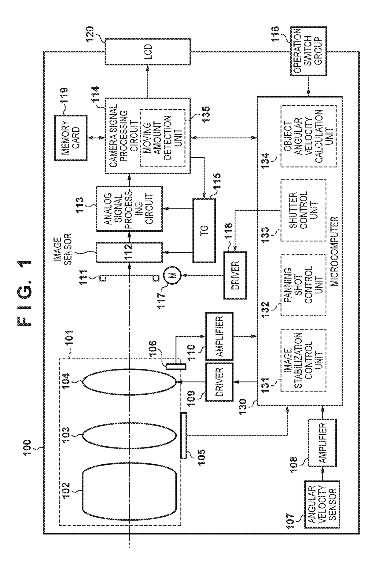
[0031]FIG. 1 is a block diagram showing a configuration of a camera that is an image capturing apparatus according to a first embodiment in which an image stabilization apparatus according to the present invention is mounted. In FIG. 1, in a camera 100, a lens is integrated in the body of the camera. However, the present invention is not limited to a camera in which a lens and the body of the camera are integrally configured, and is also applicable to a single-lens reflex camera configured such that a lens is detachably attached to the body of the camera.

[0032]The camera 100 includes a capturing lens unit 101 including a main capturing optical system 102, a zoom lens group 103 capable of changing the focal distance, and a shift lens group 104 that optically corrects an image blur with respect to the optical axis caused by camera vibration by moving in a direction perpendicular to the optical axis. The capturing lens unit 101 forms an object image on an image sensor 112, which w...

second embodiment

[0065

[0066]Hereinafter, an image capturing apparatus according to a second embodiment of the present invention will be described. FIG. 14 is a diagram showing accumulated information generated by an object angular velocity calculation unit 134 according to the second embodiment. In the second embodiment, the operation of the object angular velocity calculation unit 134 is different from that of the first embodiment. In the first embodiment, in S1504, the angular velocity is held for each frame, and only the most recent coordinates are held, whereas in the second embodiment, both the angular velocity and the coordinates are held for each frame.

[0067]FIG. 15 is a flowchart illustrating an operation performed by a moving amount detection unit 135 according to the second embodiment. A difference from the operation of the first embodiment is that the processing of S110 is added between steps S107 and S108. After information has been transmitted to the object angular velocity calculation ...


PUM


Abstract

An image stabilization apparatus includes: a first detection unit that detects object moving amounts at a plurality of positions on a screen; a determination unit that determines an object range on the screen based on a result of detection performed by the first detection unit; a holding unit that holds object position information regarding an object position within the object range in association with moving amount information at the object position based on the result of detection performed by the first detection unit and a result of detection performed by a second detection unit that detects a motion of the apparatus; and a control unit that controls an operation of an image stabilization unit that corrects object image blur at the object position held in the holding unit.

Description

BACKGROUND OF THE INVENTION[0001]Field of the Invention[0002]The present invention relates to an image blur correction technique of an image capturing apparatus for correcting an image blur generated at the time of capturing a panning shot.[0003]Description of the Related Art[0004]Conventionally, a technique called panning shot capturing is known as a photography technique that represents a sense of speed of a moving object. This photography technique is intended to obtain images in which the moving object remains stationary while the background is blurred by a photographer panning the camera along with the motion of the object. At the time of panning shot capturing, the photographer needs to pan the camera along with the motion of the object. However, it is often the case that if the panning speed is too high or too low, a difference occurs between the moving speed of the object and the panning speed, resulting in images in which the object is blurred.[0005]To address this, Japanes...

Claims


Application Information

Patent Timeline
Patent Type & Authority Patents(United States)
IPC IPC(8): H04N5/228H04N5/232G02B27/64H04N5/235
CPCH04N5/23222G02B27/646H04N5/23261H04N5/23287H04N5/23258H04N5/2353H04N23/682H04N23/6811H04N23/687H04N23/64H04N23/6815H04N23/6812H04N23/73
Inventor MUKUNASHI, MASAYUKI
Owner CANON KK
Why Eureka
Try Eureka