Oral Cavity Suction System

a suction system and oral cavity technology, applied in the field of oral cavity suction system, can solve the problems of inconvenient tubing running, unusable ejector, uncomfortable patient sensation, etc., and achieve the effect of improving the saliva ejector system and increasing the suction potential

Active Publication Date: 2017-06-08
REYES HARI MARK
View PDF5 Cites 8 Cited by
  • Summary
  • Abstract
  • Description
  • Claims
  • Application Information

AI Technical Summary

Benefits of technology

[0007]In accordance with various embodiments, an improved saliva

Problems solved by technology

If the tip of the suction tube contacts the patient's mouth tissue, it can suck the tissue into contact with the tip of the ejector, thereby rendering the ejector useless, since it is no longer removing ex

Method used


Image

  • Oral Cavity Suction System
  • Oral Cavity Suction System
  • Oral Cavity Suction System

Examples


Embodiment Construction

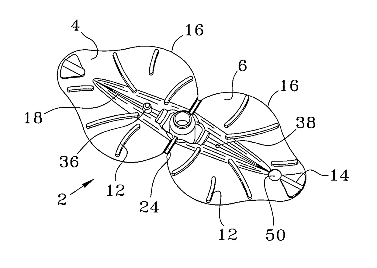
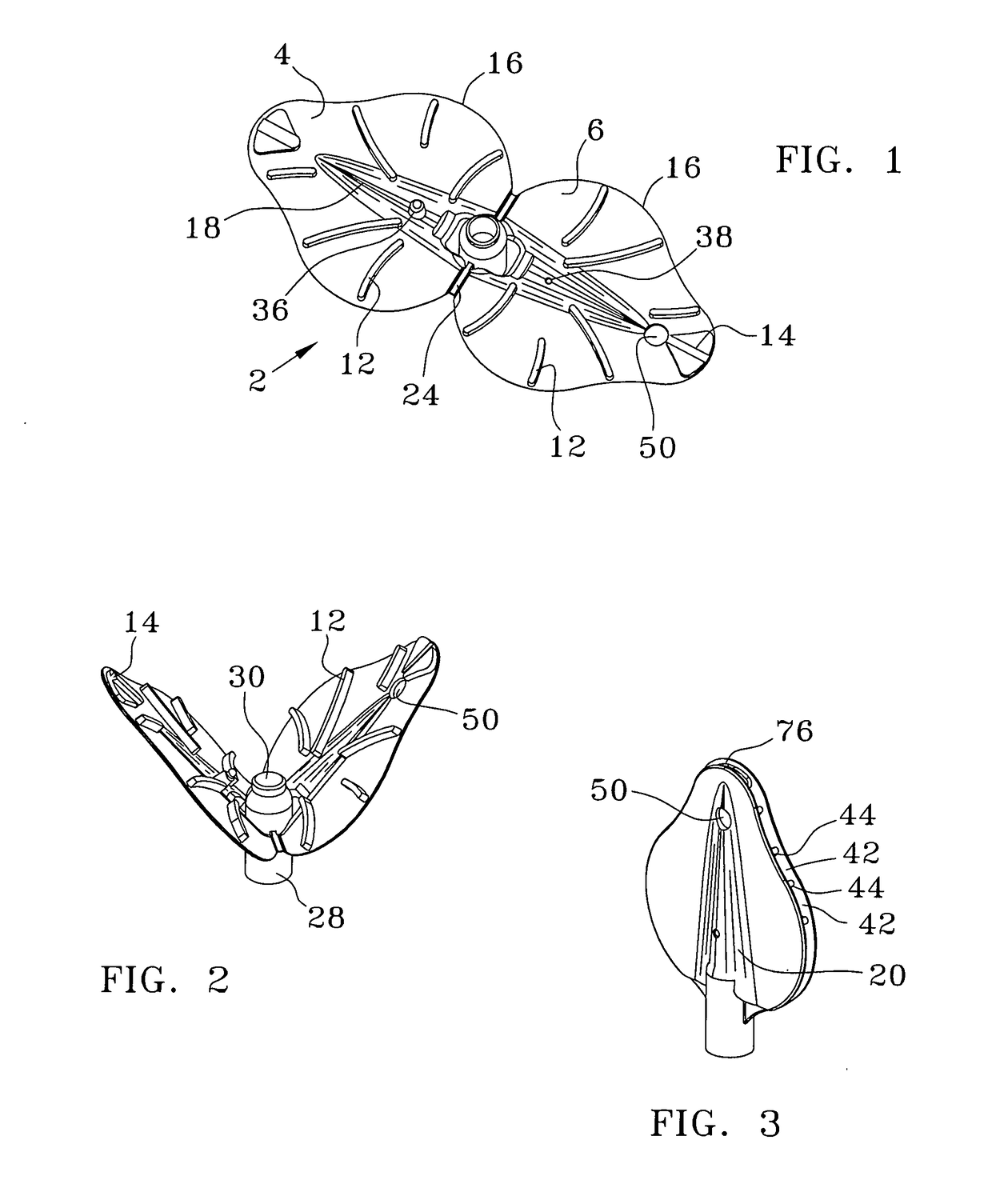
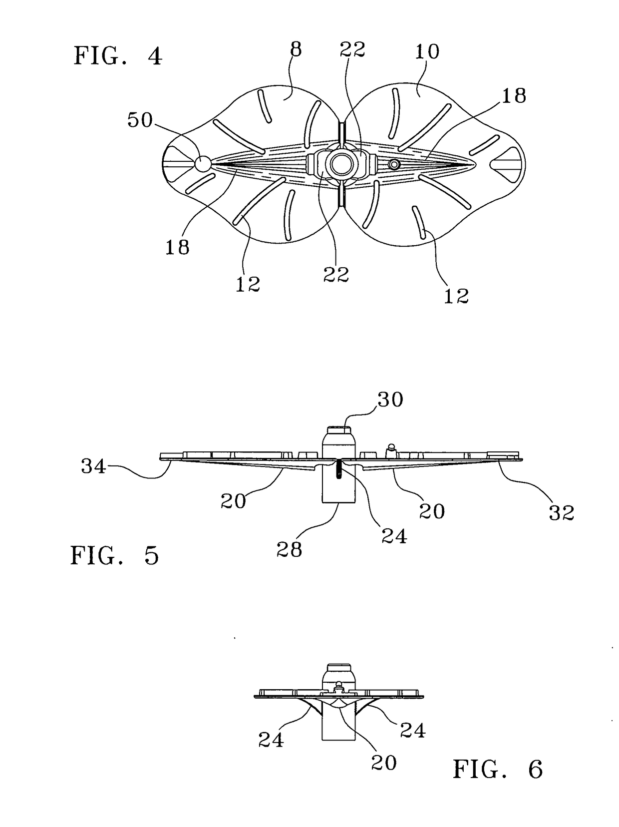
[0034]Looking at FIG. 1 it can be seen that the saliva ejector 2 is a pair of substantially planar, similar leaf shaped (ovate) plates with their proximal ends hingedly connected together into a mirror image configuration with a short tube extending normally above and below the plates from a cutout region at the center of the ejector's axial centerline, where the two plates are conjoined. When assembled, by virtue of interlocking dovetailed raised pads at the tip of each ovate plate and a central circular tab and slot, the conjoined ovate plates define a salvia flow system that allows the evacuation of the salvia from the device via a suction / vacuum system. (The saliva flow system is made of a series of flow channels and a central trough.) However, upon closer examination it can be seen that this device is much more structurally complex as will be discussed herein. (It is to be noted that vacuum and suction are used interchangeably herein.)

[0035]The saliva ejection system 60 (FIG. 1...


PUM


Abstract

An oral cavity suction system that incorporates a disposable saliva ejector residing along the interior of the patient's cheek that utilizes a single planar, double leaf shaped plate design that is embossed on their inner faces with a series of arced ribs and folded about its midpoint. The arced ribs form a series of channels about perimeter of the device that directs saliva into a trough running along the linear axis of both of the plates to direct this saliva into a connected “U” connector that hooks around the patient's cheek. A sterile suction tube is also connected on one end to the “U” connector suction tube and on its other end to a quick connect fitting that mates to a tube adapted with a fitting for connection to a high volume suction pump.

Description

PREVIOUS APPLICATIONS[0001]This patent is a Continuation in Part of pending U.S. Utility application Ser. No. 15 / 146567 filed May 4, 2016 Entitled “IMPROVED ORAL CAVITY SUCTION DEVICE” and incorporates it in its entirety herein by reference. This also claims priority from provisional patent 62 / 263867 titled the same and filed Dec. 7, 2015.COPYRIGHT STATEMENT[0002]A portion of the disclosure of this patent document contains material that is subject to copyright protection. The copyright owner has no objection to the facsimile reproduction by anyone of the patent document or the patent disclosure as it appears in the Patent and Trademark Office patent file or records, but otherwise reserves all copyright rights whatsoever.FIELD[0003]The present disclosure relates, in general, to an oral cavity suction system, and more particularly to a set of hoses, and three different quick connect couplings connectable to a dental saliva ejection device for a sanitary saliva ejection system.BACKGROU...

Claims


Application Information

Patent Timeline
IPC IPC(8): A61C17/06A61C5/14
CPCA61C5/14A61C17/043A61C17/08A61C5/90
Inventor REYES, HARI MARK
Owner REYES HARI MARK
Why Eureka
Try Eureka