Electronic device provided with an antenna integrated into a heatsink

a technology of electromagnetic radiation and heatsink, applied in the direction of cooling/ventilation/heating modifications, antenna equipment with additional functions, and modifications by conduction heat transfer, etc., to achieve the effect of improving performan

Active Publication Date: 2017-11-30
SAGEMCOM BROADBAND
View PDF3 Cites 0 Cited by
  • Summary
  • Abstract
  • Description
  • Claims
  • Application Information

AI Technical Summary

Benefits of technology

[0005]An object of the invention is to provide an electronic device presen

Problems solved by technology

Unfortunately, numerous devices incorporate elements that are solid and electrically conductive, such as a he

Method used


Image

  • Electronic device provided with an antenna integrated into a heatsink
  • Electronic device provided with an antenna integrated into a heatsink

Examples


Embodiment Construction

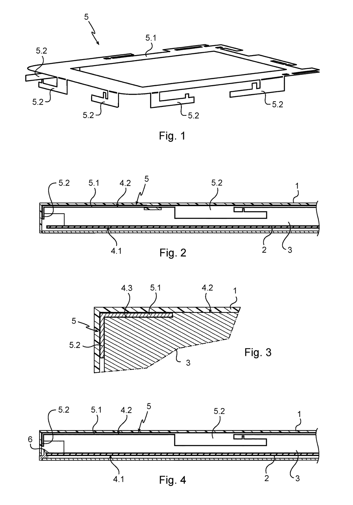
[0017]With reference to the figures, the electronic device of the invention comprises a box 1 containing an electronic card 2 and a passive heatsink 3.

[0018]The box 1 is of conventional type, and for example it is generally of rectangular box shape. The box 1 is made of an electrically insulating material, in this example a thermoplastic material.

[0019]In conventional manner, the electronic card 2 comprises a printed circuit board having electronic components mounted thereon. The electronic device also includes a power supply unit connected to the electronic card 2 and provided with means for connection to the electricity network, and an input / output unit enabling the electronic card 2 to exchange signals with the outside.

[0020]The heatsink 3 has a first face 4.1 pressed against the components of the electronic card 2, and it has an opposite second face 4.2 in contact with the box 1. The heatsink 3 is made of thermally conductive material, in this example of a metal such as aluminum...


PUM


Abstract

Electronic device including a housing enclosing an electronic board and a heatsink having a first face applied against the electronic board and, opposite, a second face making contact with the housing, an antenna being electrically connected to the electronic board and extending flatly between the heatsink and the housing while making contact with the heatsink and the housing.

Description

BACKGROUND OF THE INVENTIONField of the Invention[0001]The present invention relates to transmitting data by electromagnetic radiation.Brief Discussion of the Related Art[0002]Electronic devices exist that comprise a box housing specifically an electronic card that is electrically connected to an antenna, and a heatsink for dissipating the heat produced by one or more electronic components of the card while they are in operation. The heatsink has a first face that is applied against the electronic card, and an opposite, second face that is in contact with the box.[0003]The antenna is generally made directly on an edge of the electronic card by etching (e.g. an inverse F antenna (IFA)) or it projects directly from an edge of the electronic card (e.g. an embedded antenna with a UFL connector).[0004]Unfortunately, numerous devices incorporate elements that are solid and electrically conductive, such as a heatsink, that mask the antenna in part, and that have an effect on its directivit...

Claims


Application Information

Patent Timeline
IPC IPC(8): H01Q1/02H01Q1/44
CPCH01Q1/44H01Q1/02H05K7/2039H05K7/20509
Inventor DEJARDIN, ROMAIN
Owner SAGEMCOM BROADBAND
Why Eureka
Try Eureka