

Dental Framework and Prosthesis
a dental framework and prosthesis technology, applied in the field of dental framework and prosthesis, can solve the problems of high level of skill and significant laboratory time, traditional hybrids breaking and fracture, and individual crown prosthesis not being an ideal option
- Summary
- Abstract
- Description
- Claims
- Application Information
AI Technical Summary
Benefits of technology
Problems solved by technology
Method used
Image

Examples
Embodiment Construction
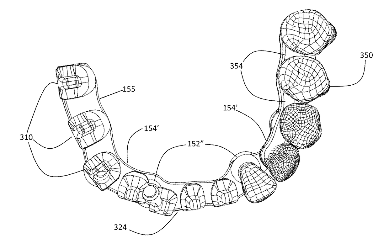
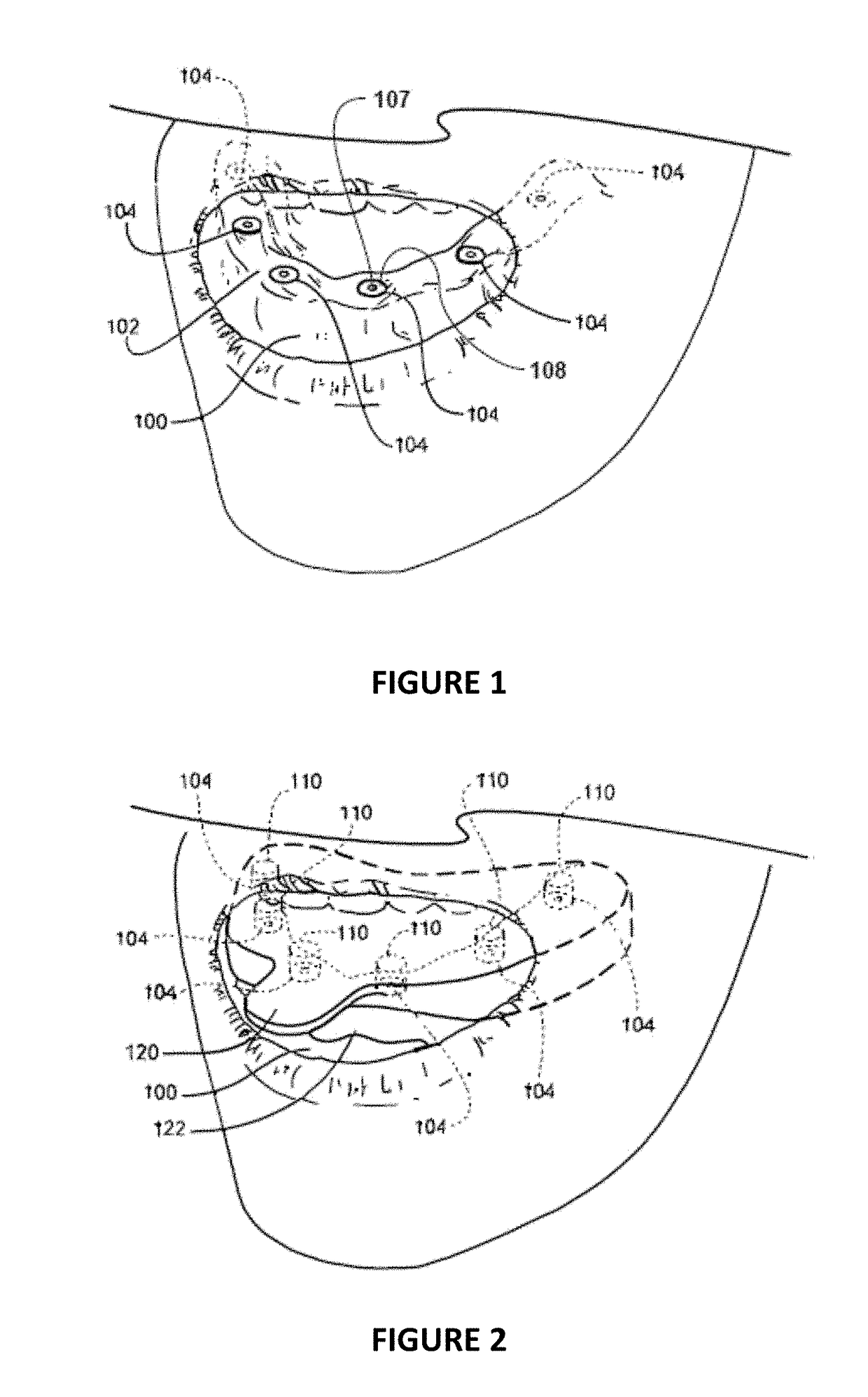
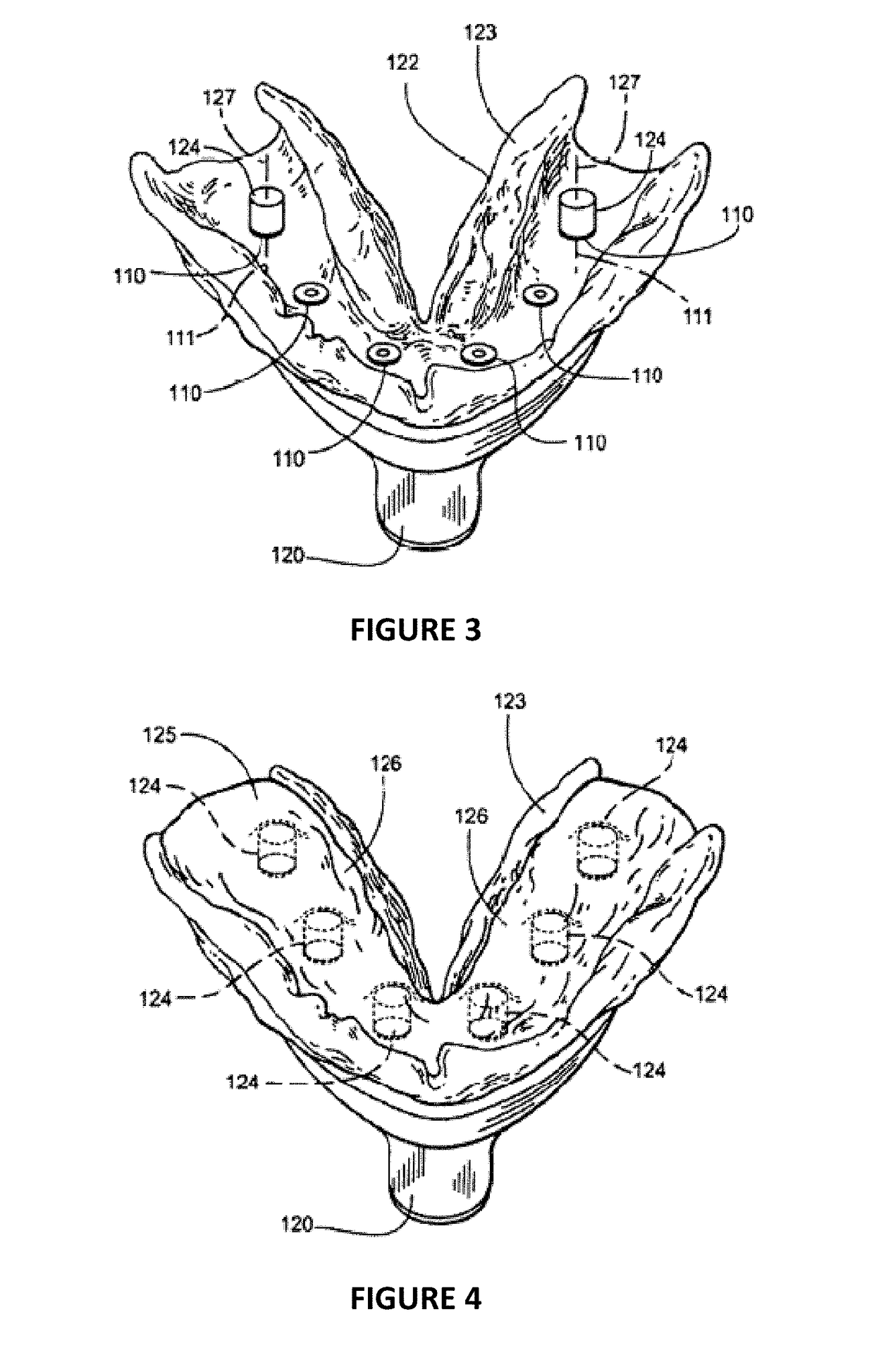
[0064]The dental prosthesis is supported by a dental framework which functions as a structural support and point of attachment. The dental framework is attached to dental anchors, such as dental implants which are secured to the patient's mandible or maxilla, the framework may be fabricated based on the dimensions and surface contours of a stone cast and diagnostic wax up created from an impression of the patient's mouth such as described in U.S. Pat. No. 8,100,692. The stone cast replicates the soft tissue contours and implant positions in the patient's mouth. The diagnostic wax up represents the final prosthesis and ultimately the position of the denture teeth to be restored for the patient. In order to create the diagnostic wax up, the dentist or technician will position upon the stone cast the stock denture teeth and wax as required for proper prosthetic function and aesthetics. The commercially available stock teeth are generally manufactured with predetermined geometries of a ...
PUM
| Property | Measurement | Unit |
|---|---|---|
| Size | aaaaa | aaaaa |
| Mechanical properties | aaaaa | aaaaa |
| Dimension | aaaaa | aaaaa |
Abstract
Description
Claims
Application Information