LED lighting circuit with controllable LED matrix

a technology of led lighting and led matrix, which is applied in the direction of lighting apparatus, electrical equipment, light sources, etc., can solve the problems of large amount of wiring and obstacle to dense packaging of led lighting devices, and achieve the effect of facilitating individual control of the activation state of led lighting devices by the control circui

Active Publication Date: 2018-02-15
KONINKLJIJKE PHILIPS NV
View PDF16 Cites 0 Cited by
  • Summary
  • Abstract
  • Description
  • Claims
  • Application Information

AI Technical Summary

Benefits of technology

[0024]In particular, a first input signal may be provided to indicate an activation or deactivation state of the first LED lighting device, and a second input signal may be provided for the second LED lighting device in the same manner. A logic circuit may be disposed to deliver switching signals at least to the first and second switching elements, preferably also to the third switching element, to activate the first and second LED lighting devices in accordance with the first and second input signals. Thus, individual control of the activation state of the LED lighting devices by the control circuit is facilitated. A logic circuit may be implemented by a digital or analogue circuit.

Problems solved by technology

Known arrays of individually controllable LEDs may require an extensive amount of wiring to connect to each of the LEDs.
This may be an obstacle for dense packaging of the LED lighting devices.

Method used


Image

  • LED lighting circuit with controllable LED matrix
  • LED lighting circuit with controllable LED matrix
  • LED lighting circuit with controllable LED matrix

Examples


Embodiment Construction

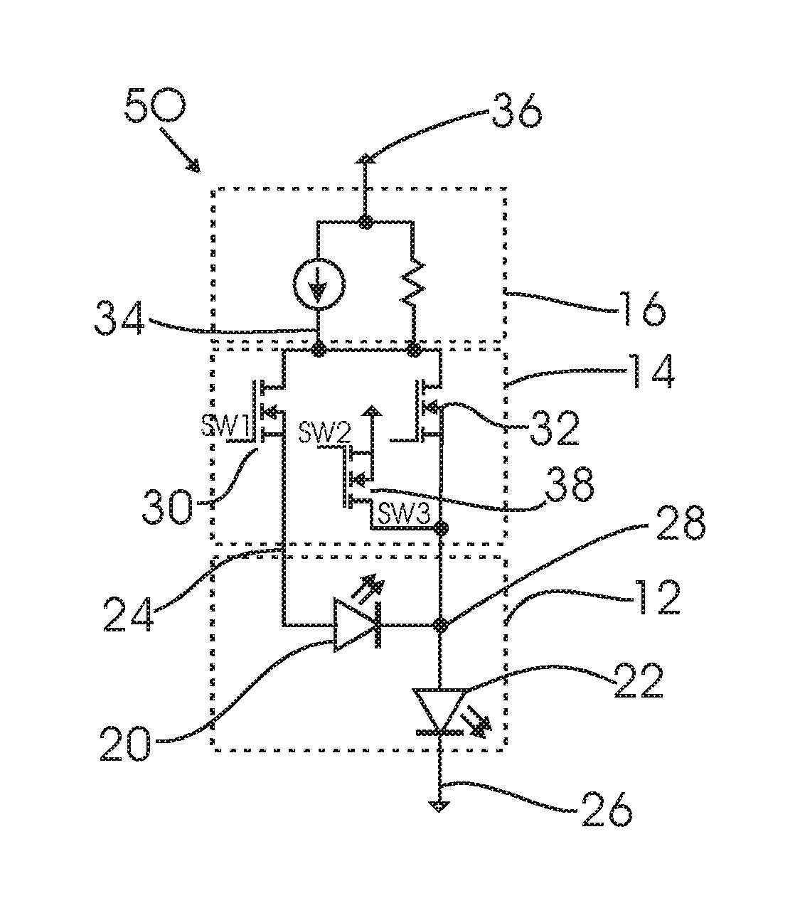
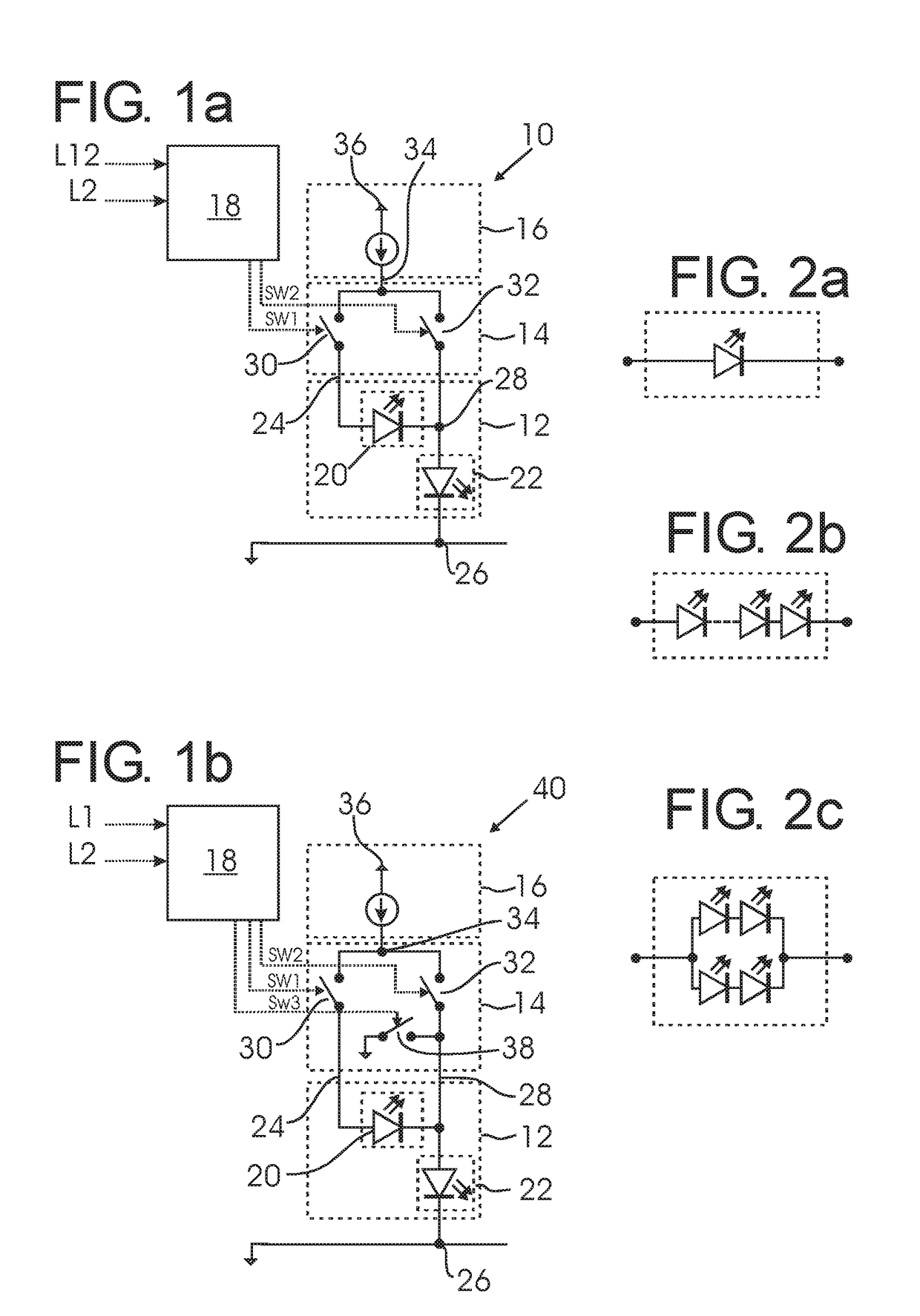
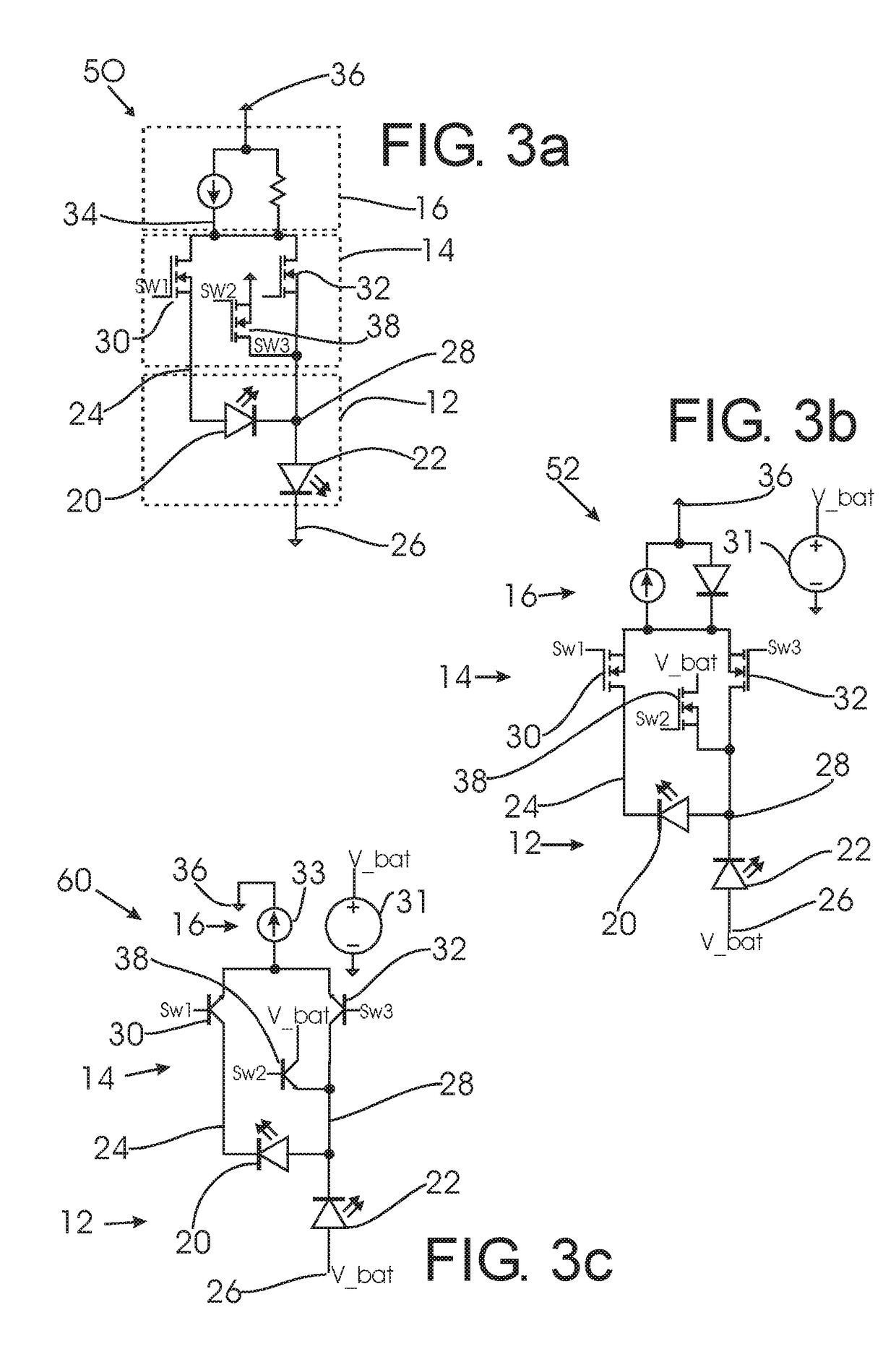
[0040]FIG. 1a shows a first circuit 10 according to a first embodiment comprising a lighting circuit 12, a switching circuit 14, a power supply 16 and a logic circuit 18.

[0041]The lighting circuit 12 comprises two LED lighting devices, a first LED lighting device 20 and a second LED lighting device 22, connected in series with a cathode of the first LED lighting device 20 connected to an anode of the second LED lighting device 22.

[0042]The lighting circuit 12 comprises three external terminals: A first lighting circuit terminal 24 connected to an anode of the first LED lighting device 20, a second lighting circuit terminal 26 connected to ground and third lighting terminal 28 connected in between the first and second LED lighting devices 20, 22, i.e. both to a cathode of the first LED lighting device 20 and an anode of the second LED lighting device 22.

[0043]The LED lighting devices 20, 22 are symbolically shown in FIG. 1a as single LED elements with two terminals, an anode and a ca...


PUM


Abstract

A circuit and a method for operating LED lighting devices are described. A first LED lighting device and a second LED lighting device are electrically connected in series between first and second lighting circuit terminals. A third lighting circuit terminal is connected between the first and second LED lighting devices. A power supply with a first and second power supply terminals for delivering electrical power to the LED lighting devices is provided. Further, a switching circuit comprises at least a first switching element and second switching element. The first switching element is connected between the first power supply terminal and the first lighting circuit terminal. The second switching element is connected between the first power supply terminal and the third lighting circuit terminal. The switching circuit receives switching signals sw1, sw2 from a control circuit.

Description

FIELD OF THE INVENTION[0001]The invention relates to a circuit for operating LED lighting devices, to a lighting device including such a circuit, and to a method of operating LED lighting devices.BACKGROUND OF THE INVENTION[0002]In an increasing number of lighting applications, LED lighting devices are used. In many of these applications, multiple LED lighting devices are employed, e.g. in the form of an array. Some applications require controllable LED lighting devices within the array.[0003]US 2013 / 0193852 A1 describes a circuit for controlling a plurality of LEDs connected in series. The circuit includes a plurality of switches, each connectable between the anode and cathode of one of the LEDs. Each of the switches has a conducting and non-conducting state. Controllers operate the switches, such that open switches turn on their associated LEDs and closed switches will turn off their associates LEDs. Several circuits may be connected together in order to control an array of LEDs.[...

Claims


Application Information

Patent Timeline
Patent Type & Authority Applications(United States)
IPC IPC(8): H05B33/08H05B44/00
CPCH05B33/0824H05B45/44H05B45/60H05B45/48
Inventor HILGERS, ACHIM
Owner KONINKLJIJKE PHILIPS NV
Why Eureka
Try Eureka