High shaft forming fabrics

a high-shaft, fabric technology, applied in the field of fabrics, can solve the problems of wire marks, undesired variations in sheet absorption properties, etc., and achieve the effect of reducing the risk of wire marks

Inactive Publication Date: 2009-08-11
VOITH PATENT GMBH
View PDF34 Cites 12 Cited by
  • Summary
  • Abstract
  • Description
  • Claims
  • Application Information

AI Technical Summary

Benefits of technology

[0039]iii) Use only a jacquard mechanism. This technique is very complex and involves high numbers of mechanism parts to facilitate the individual control of each warp yarn. Consequently, high maintenance costs may be generated and costly machine stops experienced in order to ensure that each of the warp yarns is maintained within required tension limits. However, using a jacquard mechanism does allow the production of fabric with extremely long binder segments to thereby minimize interchange points per unit fabric area and ensure that the potential to wiremark is reduced.
[0041]Surprisingly, applicants have found that utilizing an irregular drawing-in sequence of the heddle frames can minimize the tension differences between adjacent warp yarns and thereby produce suitable fabric for high quality paper production. An irregular drawing-in sequence of the heddle frames means that the warps are not arranged sequentially from first frame to last frame, as is the custom in the manufacture of forming fabric, but instead the heddle allocation is rearranged such that adjacent warp yarns are less likely to be controlled by frames which will exert significantly different levels of tension on the respective yarns.
[0043]The maximum number of frames between adjacent warp yarns in the fabrics of this invention can be reduced by use of a “fancy” or irregular draw-in. For example, in the above-described case of a 40 shaft fabric, an illustrative, but not limiting, fancy draw-in could involve drawing-in frame 1 to frame 20 in sequence as before. However, warps 21 to 40 would be drawn-in following a reversed order i.e. warp 21 allocated to frame 40 and warp 40 allocated to frame 21. In this way, a 40 shaft fabric of this invention can be made with the largest number of frames between adjacent yarns being reduced to the 19 of the prior art 20 shaft fabrics.
[0067]This ratio compares the number of binder pair interchange points in the paper side weave repeat, for a representative binder pair, with the wear side weave repeat size. This value can give some indication of the potential of a structure to allow spacing apart of the binder interchange points and the wear side weave knuckles. Weave structures which can avoid closely grouping such features may have a reduced wire mark risk.

Problems solved by technology

Such localized penetration results in “wire marks,” which actually are the result of basis weight variations throughout the sheet area.
Moreover, these basis weight variations can result in undesired variations in sheet absorption properties; a property very relevant to the functionality of quality graphical papers where a consistent uptake of print ink is necessary to produce a clear sharp image.
Other factors also cause the formation of undesired wire marks.
However, the use of thick yarns to establish such a high mass often causes undesirable wire marks.
The location of such yarn mass areas within the fabric inner region reduces the ability of water to flow through the fabric in such yarn mass areas such that fabric dewatering may be adversely effected.
The relatively high “void volume” is typically associated with sheet re-wetting on the paper machine such that the sheet solids content at transfer to the press section may be undesirably low.
That is, the fibrous web formed on the papermaking fabric has an undesirably low fiber-to-weight ratio.
This can result in reduced machine performance through a higher amount of sheet breaks occasioned by the wetter sheet, reduced running speed and higher drying costs downstream of initial web formation on the papermaking fabric.
The disturbance can contribute to the formation of undesired sheet wire marks.
Furthermore, the weave patterns employed in the wear side layers of the above-mentioned prior art fabrics do not provide the desired wear resistance for enhanced fabric life.
Specifically, these prior art wear side fabric weave patterns have been relatively small, e.g., five or six shaft repeats, such that fabric life potential may be restricted.
Moreover, these small shaft repeats create an undesired high frequency of wear side weft knuckles located in the fabric interior, which interferes with the flow of water through the fabric.
However, the wear side layer weaves disclosed in the Troughton '306 patent utilize multiple warp interlacings with each wearside weft yarn such that there is still an undesirably high amount of wearside weft knuckle material appearing in the fabric interior.
Furthermore, the fabrics disclosed in the Troughton '306 patent all have a high frequency of paperside transition points (described in detail hereinafter) and so do not resolve the problem of wire marks stemming from the transitional regions.
In addition, this interaction of the wear side warp yarns with the wear side weft yarns in the inside of the fabric creates a high tendency to interfere with, and create non-uniformity of water flow through the fabric.
This can result in irregularities in the formed sheet.

Method used


Image

  • High shaft forming fabrics
  • High shaft forming fabrics
  • High shaft forming fabrics

Examples


first embodiment

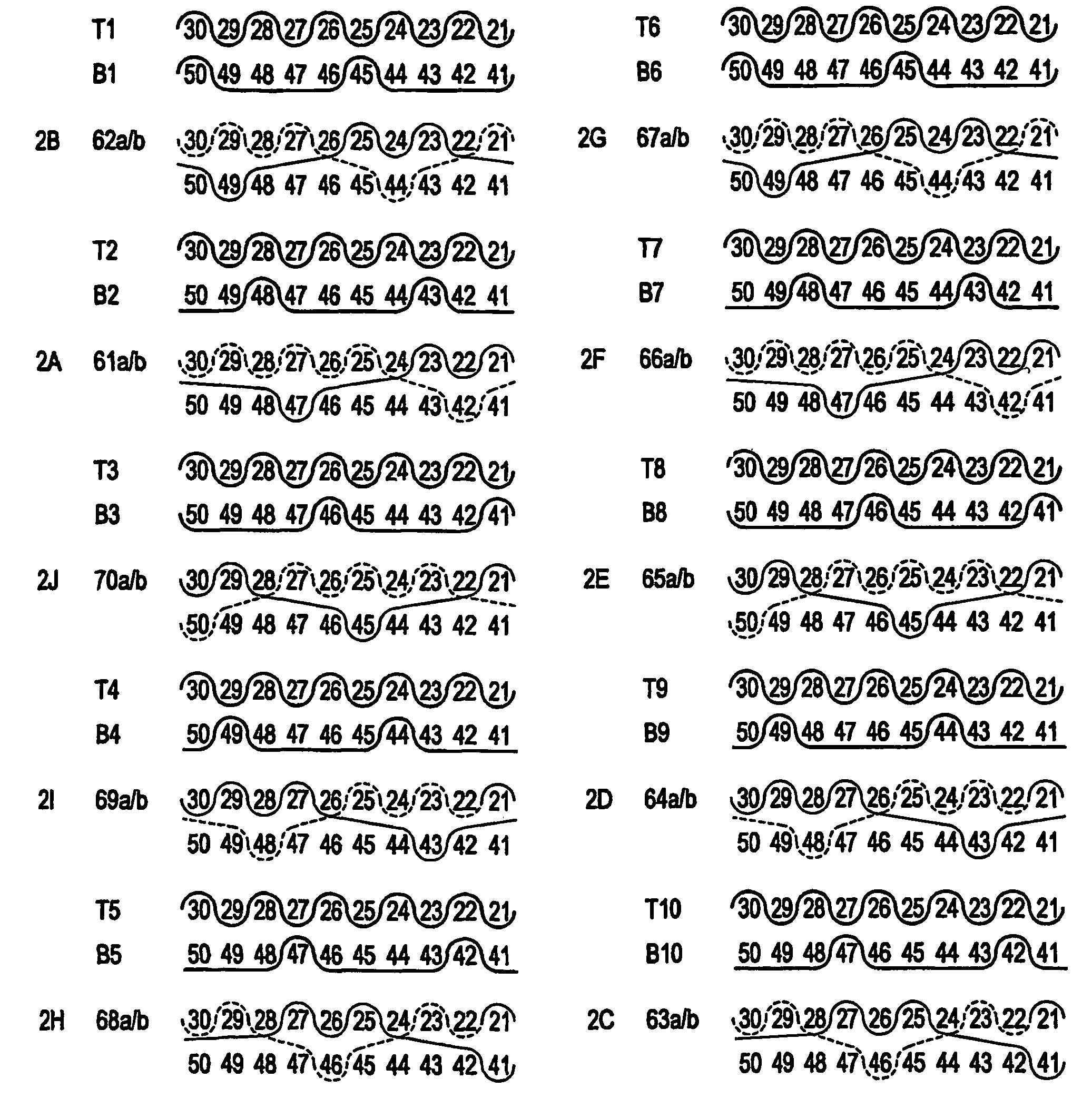
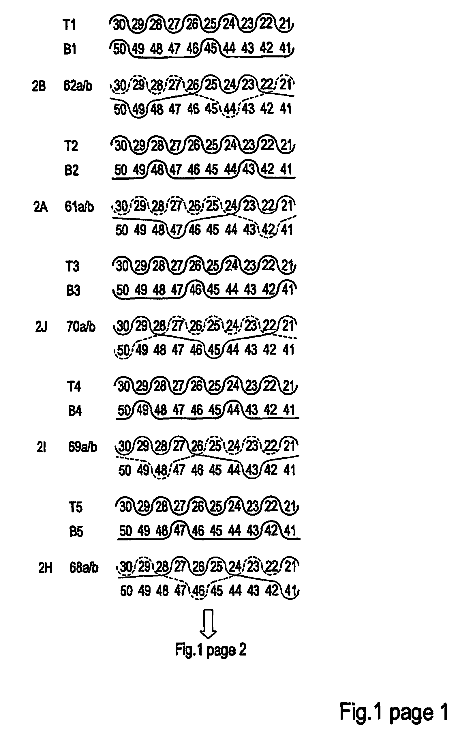
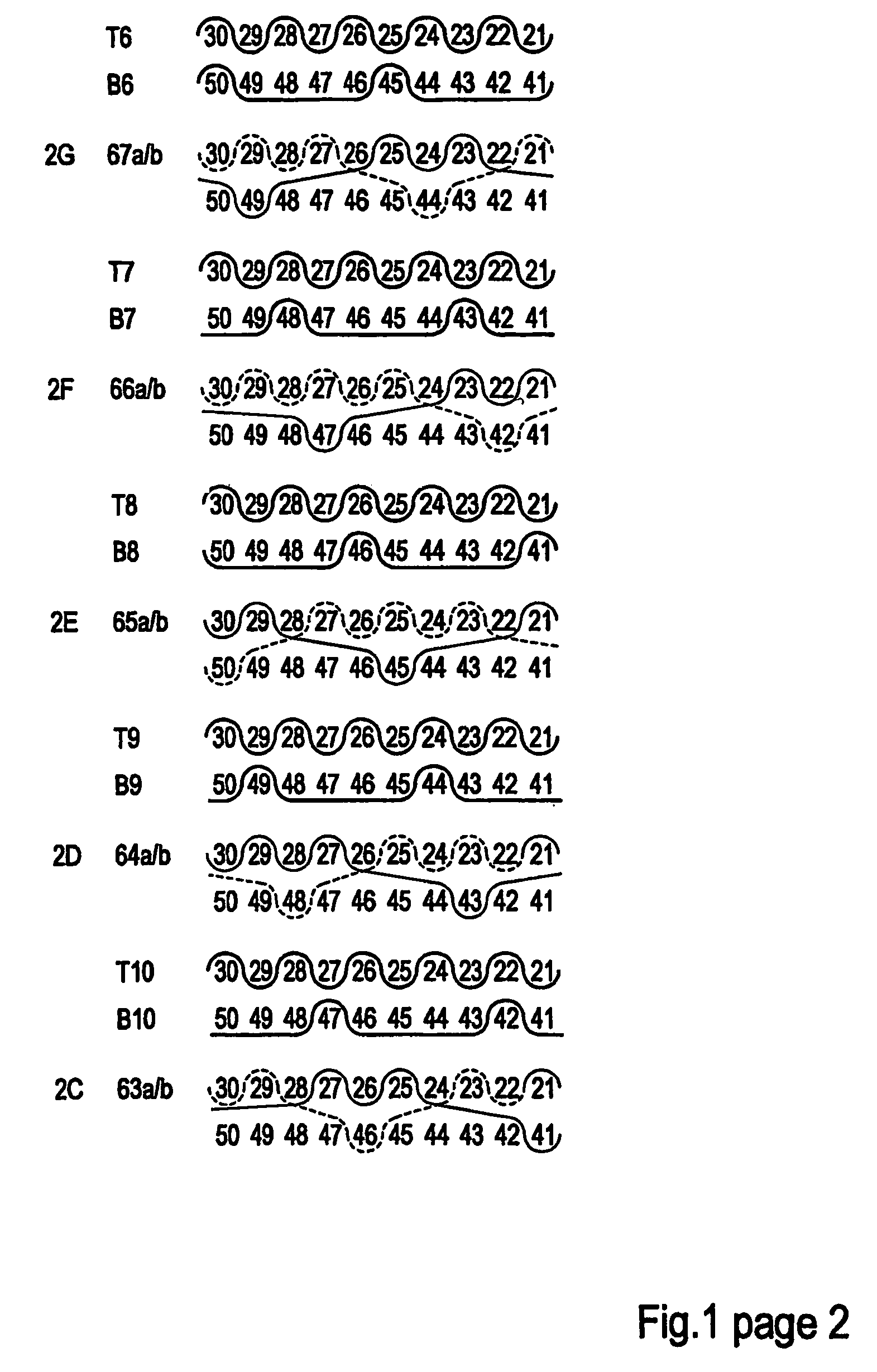
[0134]Referring to FIG. 2, a fabric in accordance with this invention is illustrated at 20; showing a single full fabric weave repeat and comprising 14 paper side wefts (T1, T2, T3 . . . T14), 14 wear side wefts (B1, B2, B3 . . . B14), and 14 pairs of interchanging, binder weft yarns (I1 / 2, I3 / 4, I5 / 6 . . . I27 / 28).

[0135]The fabric 20 has a twenty (28) shaft repeat, including a fourteen (14) warp top layer (1, 3, 5, . . . 27) having a paper side surface within each repeat, a fourteen (14) warp machine side layer (2, 4, 6, . . . 28) having a bottom wear side surface within each repeat and a plurality of pairs of first and second intrinsic interchanging weft binder yarns (I1 / 2 through I27 / 28).

[0136]As illustrated in the weft path weave patterns depicted in FIG. 2, the top layer includes top warp yarns 1, 3, 5 . . . 27 within each repeat interwoven with top, i.e., paper side, weft yarns T1, T2 . . . T14 and top segments of the interlacing binder pairs I1 / 2, I3 / 4, I5 / 6 . . . I27 / 28 to f...

second embodiment

[0150]Referring to FIG. 3, a fabric in accordance with this invention is illustrated at 30; showing the full weave paths for all paper side wefts (T1, T2, T3 . . . T14), wear side wefts (B1, B2, B3 . . . B14), and interchanging binder weft pairs (I1 / 2, I3 / 4, I5 / 6 . . . I27 / 28). As will be discussed in detail hereinafter, except for the arrangement of the interchanging binder pairs, the fabric 30 is the same as the fabric 20.

[0151]Specifically the fabric 30, like the fabric 20, has a twenty-eight (28) shaft repeat, including a fourteen (14) warp top layer (1, 3, 5, . . . 27) having a paper side surface within each repeat, a fourteen (14) warp machine side layer (2, 4, 6, . . . 28) having a bottom wear side surface within each repeat and a plurality of pairs of first and second intrinsic interchanging weft binder yarns (I1 / 2 through I27 / 28).

[0152]As illustrated in the weft path weave patterns depicted in FIG. 3, the top layer includes top warp yarns 1, 3, 5 . . . 27 within each repeat...

third embodiment

[0166]Referring to FIG. 4, a fabric in accordance with this invention is a 28 shaft repeat and is illustrated at 40; showing the full weave paths for all paper side wefts (T1, T2, T3 . . . T14), wear side wefts (B1, B2, B3 . . . B14), and interchanging binder weft pairs (I1 / 2, I3 / 4, I5 / 6 . . . I27 / 28). As will be discussed in detail hereinafter, except for the arrangement of the interchanging binder pairs, the fabric 40 is the same as the fabrics 20 and 30.

[0167]Specifically the fabric 40, like the fabrics 20 and 30, has a twenty eight (28) shaft repeat, including a fourteen (14) warp top layer (1, 3, 5, . . . 27) having a paper side surface within each repeat, a fourteen (14) warp machine side layer (2, 4, 6, . . . 28) having a bottom wear side surface within each repeat and a plurality of pairs of first and second intrinsic interchanging weft binder yarns (I1 / 2 through I27 / 28).

[0168]As illustrated In the weft path weave patterns depicted in FIG. 4, the top layer includes top warp ...


PUM


Abstract

A paper making composite forming fabric including paper side weft and warp yarns and wear side warp yarns and bindery yarns. The paper side wefts and the binder yarns being interwoven with the paper side warp yarns. The binder yarns being interwoven with the wear side warps. A total number of paper side and wear side warp yarns per weave repeat is greater than 24. An internal binder float length is between 2 and 4. The fabric has an interchange points percentage value of less than 20 and a binder interchange points as a percentage of total machine direction yarns value of less than 10.

Description

FIELD OF THE INVENTION[0001]The present invention relates to fabrics, and more particularly to fabrics made with a high weave repeat number and employed in web forming equipment, such as papermaking and non-woven web-forming equipment. More particularly, the preferred fabrics of this invention are employed as forming fabrics in web forming equipment; most preferably in papermaking machines employed to make graphical paper having desired properties suitable for effectively receiving printing ink thereon.BACKGROUND OF THE INVENTION[0002]Papermaking involves the forming, pressing and drying of cellulosic fiber sheets. The forming process includes the step of depositing an aqueous stock solution of the fibers, and possibly other additives, onto the forming fabric upon which the initial paper web is formed. The forming fabric may run on a so-called Gap Former machine in which the aqueous stock initially is de-watered, and the initial paper sheet is formed between two forming fabrics.[000...

Claims


Application Information

Patent Timeline
Patent Type & Authority Patents(United States)
IPC IPC(8): D21F1/10D21F7/08D03D25/00D03D11/00D21F1/00
CPCD21F1/0045
Inventor HAY, STEWART LISTERWESTERKAMP, ARVED
Owner VOITH PATENT GMBH
Why Eureka
Try Eureka