High Shaft Forming Fabrics

a technology of high shaft and fabric, applied in the field of fabrics, can solve the problems of undesired variations in sheet absorption properties, wire marks, and undesired wire marks

Inactive Publication Date: 2008-02-14
VOITH PATENT GMBH
View PDF28 Cites 13 Cited by
  • Summary
  • Abstract
  • Description
  • Claims
  • Application Information

AI Technical Summary

Benefits of technology

[0059]This further refines the ratio IWR by accounting for the actual number of wear side fabric MD-CD interlacings. By using WKR we can identify more accurately, for fabrics with comparable paper side weave types and number of binder yarn interchange points, the influence of the wear side weft knuckles. Again care must be taken in interpreting the significance of values obtained for WKR. A value of >1 for WKR indicates a structure with, on average, more paper side interchange points per binder pair than wear side fabric MD-CD interlacings per weft yarn. A WKR value of <1 indicates a structure with, on average, more wear side fabric MD-CD interlacings per weft yarn than interchange points per interchanging binder yarn pair. This knowledge is useful in determining the best fabric to supply to a customer.

Problems solved by technology

Such localized penetration results in “wire marks,” which actually are the result of basis weight variations throughout the sheet area.
Moreover, these basis weight variations can result in undesired variations in sheet absorption properties; a property very relevant to the functionality of quality graphical papers where a consistent uptake of print ink is necessary to produce a clear sharp image.
Other factors also cause the formation of undesired wire marks.
However, the use of thick yarns to establish such a high mass often causes undesirable wire marks.
The location of such yarn mass areas within the fabric inner region reduces the ability of water to flow through the fabric in such yarn mass areas such that fabric dewatering may be adversely effected.
The relatively high “void volume” is typically associated with sheet re-wetting on the paper machine such that the sheet solids content at transfer to the press section may be undesirably low.
That is, the fibrous web formed on the papermaking fabric has an undesirably low fiber-to-weight ratio.
This can result in reduced machine performance through a higher amount of sheet breaks occasioned by the wetter sheet, reduced running speed and higher drying costs downstream of initial web formation on the papermaking fabric.
The disturbance can contribute to the formation of undesired sheet wire marks.
Furthermore, the weave patterns employed in the wear side layers of the above-mentioned prior art fabrics do not provide the desired wear resistance for enhanced fabric life.
Specifically, these prior art wear side fabric weave patterns have been relatively small, e.g., five or six shaft repeats, such that fabric life potential may be restricted.
Moreover, these small shaft repeats create an undesired high frequency of wear side weft knuckles located in the fabric interior, which interferes with the flow of water through the fabric.
However, the wear side layer weaves disclosed in the Troughton '306 patent utilize multiple warp interlacings with each wearside weft yarn such that there is still an undesirably high amount of wearside weft knuckle material appearing in the fabric interior.
Furthermore, the fabrics disclosed in the Troughton '306 patent all have a high frequency of paperside transition points (described in detail hereinafter) and so do not resolve the problem of wire marks stemming from the transitional regions.
In addition, this interaction of the wear side warp yarns with the wear side weft yarns in the inside of the fabric creates a high tendency to interfere with, and create non-uniformity of water flow through the fabric.
This can result in irregularities in the formed sheet.

Method used


Image

  • High Shaft Forming Fabrics
  • High Shaft Forming Fabrics
  • High Shaft Forming Fabrics

Examples


first embodiment

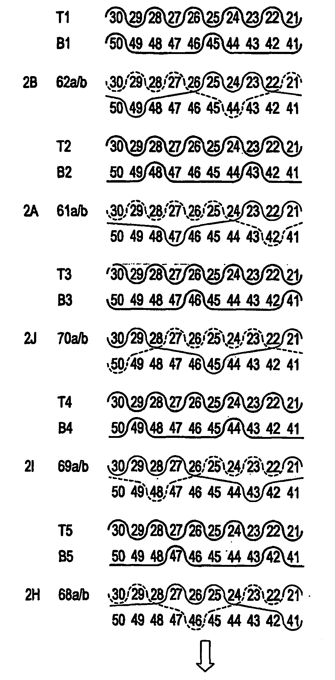
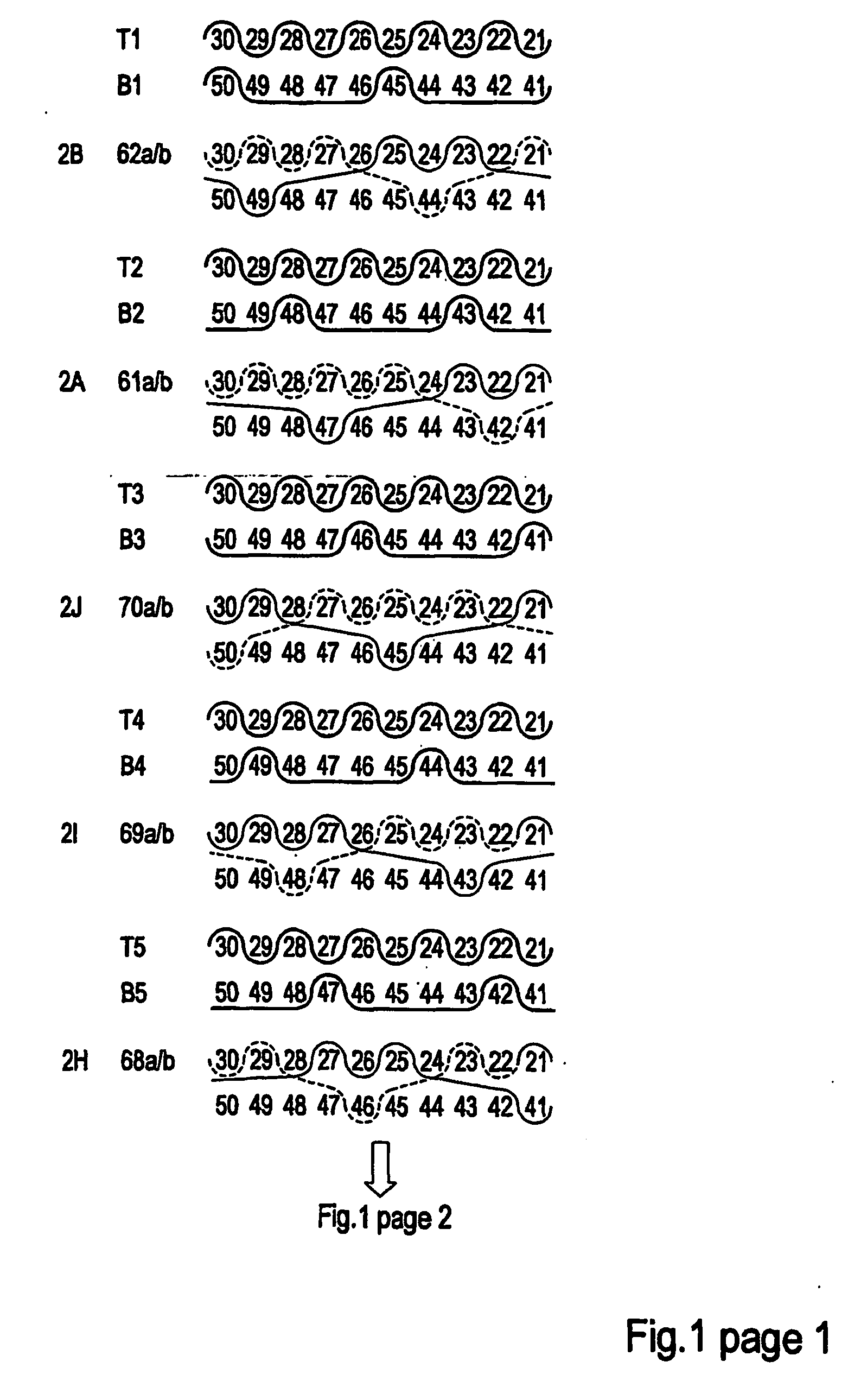
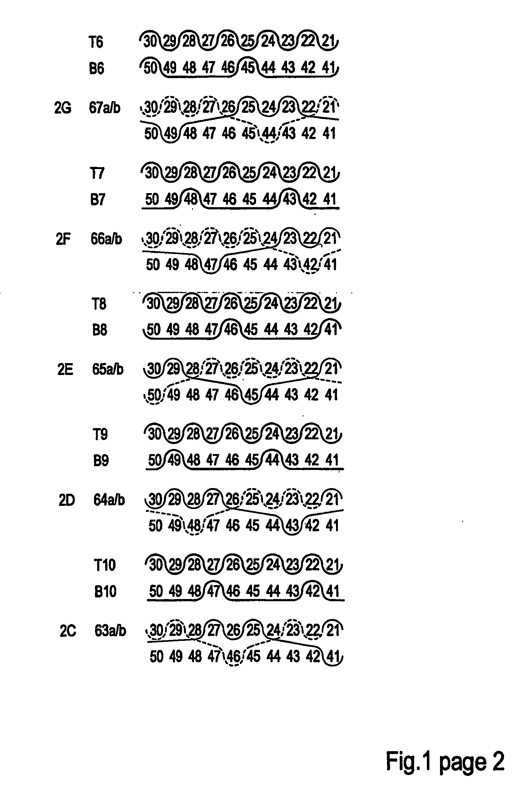
[0121]Referring to FIG. 2, a fabric in accordance with this invention is illustrated at 20; showing a single full fabric weave repeat and comprising 14 paper side wefts (T1, T2, T3 . . . T14), 14 wear side wefts (B1, B2, B3 . . . B14), and 14 pairs of interchanging, binder weft yarns (I1 / 2, I3 / 4, I5 / 6 . . . I27 / 28).

[0122]The fabric 20 has a twenty (28) shaft repeat, including a fourteen (14) warp top layer (1, 3, 5, . . . 27) having a paper side surface within each repeat, a fourteen (14) warp machine side layer (2, 4, 6, . . . 28) having a bottom wear side surface within each repeat and a plurality of pairs of first and second intrinsic interchanging weft binder yarns (I1 / 2 through I27 / 28).

[0123]As illustrated in the weft path weave patterns depicted in FIG. 2, the top layer includes top warp yarns 1, 3, 5 . . . 27 within each repeat interwoven with top, i.e., paper side, weft yarns T1, T2 . . . T14 and top segments of the interlacing binder pairs I1 / 2, I3 / 4, I5 / 6 . . . I27 / 28 to f...

second embodiment

[0137]Referring to FIG. 3, a fabric in accordance with this invention is illustrated at 30; showing the full weave paths for all paper side wefts (T1, T2, T3 . . . T14), wear side wefts (B1, B2, B3 . . . B14), and interchanging binder weft pairs (I1 / 2, I3 / 4, I5 / 6 . . . I27 / 28). As will be discussed in detail hereinafter, except for the arrangement of the interchanging binder pairs, the fabric 30 is the same as the fabric 20.

[0138]Specifically the fabric 30, like the fabric 20, has a twenty-eight (28) shaft repeat, including a fourteen (14) warp top layer (1, 3, 5, . . . 27) having a paper side surface within each repeat, a fourteen (14) warp machine side layer (2, 4, 6, . . . 28) having a bottom wear side surface within each repeat and a plurality of pairs of first and second intrinsic interchanging weft binder yarns (I1 / 2 through I27 / 28).

[0139]As illustrated in the weft path weave patterns depicted in FIG. 3, the top layer includes top warp yarns 1, 3, 5 . . . 27 within each repeat...

third embodiment

[0153]Referring to FIG. 4, a fabric in accordance with this invention is a 28 shaft repeat and is illustrated at 40; showing the full weave paths for all paper side wefts (T1, T2, T3 . . . T14), wear side wefts (B1, B2, B3 . . . B14), and interchanging binder weft pairs (I1 / 2, I3 / 4, I5 / 6 . . . I27 / 28). As will be discussed in detail hereinafter, except for the arrangement of the interchanging binder pairs, the fabric 40 is the same as the fabrics 20 and 30.

[0154]Specifically the fabric 40, like the fabrics 20 and 30, has a twenty eight (28) shaft repeat, including a fourteen (14) warp top layer (1, 3, 5, . . . 27) having a paper side surface within each repeat, a fourteen (14) warp machine side layer (2, 4, 6, . . . 28) having a bottom wear side surface within each repeat and a plurality of pairs of first and second intrinsic interchanging weft binder yarns (I1 / 2 through I27 / 28).

[0155]As illustrated In the weft path weave patterns depicted in FIG. 4, the top layer includes top warp ...


PUM

PropertyMeasurementUnit
lengthaaaaaaaaaa
weight ratioaaaaaaaaaa
heightaaaaaaaaaa

Abstract

Paper making composite forming fabric comprising paper side weft and warp yarns, wear side warp yarns and binder yarns, wherein the paper side wefts and the binder yarns are interwoven with the paper side warp yarns, and wherein the binder yarns are interwoven with the wear side warps, wherein the total number of paper side and wear side warp yarns per weave repeat is greater than 24.

Description

FIELD OF THE INVENTION[0001]The present invention relates to fabrics, and more particularly to fabrics made with a high weave repeat number and employed in web forming equipment, such as papermaking and non-woven web-forming equipment. More particularly, the preferred fabrics of this invention are employed as forming fabrics in web forming equipment; most preferably in papermaking machines employed to make graphical paper having desired properties suitable for effectively receiving printing ink thereon.BACKGROUND OF THE INVENTION[0002]Papermaking involves the forming, pressing and drying of cellulosic fiber sheets. The forming process includes the step of depositing an aqueous stock solution of the fibers, and possibly other additives, onto the forming fabric upon which the initial paper web is formed. The forming fabric may run on a so-called Gap Former machine in which the aqueous stock initially is de-watered, and the initial paper sheet is formed between two forming fabrics.[000...

Claims


Application Information

Patent Timeline
Patent Type & Authority Applications(United States)
IPC IPC(8): D21F13/00D03D11/00D21F1/00
CPCD21F1/0045
Inventor HAY, STEWART LISTERWESTERKAMP, ARVED
Owner VOITH PATENT GMBH
Why Eureka
Try Eureka