Active cooling for a concentrated photovoltaic cell

a photovoltaic cell and active cooling technology, applied in the direction of generator/motor, thermal-pv hybrid energy generation, semiconductor devices, etc., can solve the problems of low efficiency of pv cells at higher temperatures, complex passive cooling, such as heat dissipation, and cost. , to achieve the effect of low efficiency of the electricity generation process

Active Publication Date: 2018-06-28
SAINT AUGUSTIN CANADA ELECTRIC
View PDF13 Cites 0 Cited by
  • Summary
  • Abstract
  • Description
  • Claims
  • Application Information

AI Technical Summary

Benefits of technology

[0010]As a result of such approach, a wasted heat harvesting device is capable of converting heat into electricity in an efficient manner.
[0047]As a result of this approach, it is possible to realize a wasted heat harvesting device with a reduced number of steps and with technology compatible with photovoltaic cell manufacturing.

Problems solved by technology

This is due to the fact that PV cells are less efficient at higher temperatures and due to the possibility of the PV cells being damaged by very high temperatures.
In order to cool down the PV cells, passive cooling, such as a heat dissipater, becomes complicated and, therefore, costly.
In the latter case, the efficiency of the electricity generation process is rather low.

Method used


Image

  • Active cooling for a concentrated photovoltaic cell
  • Active cooling for a concentrated photovoltaic cell
  • Active cooling for a concentrated photovoltaic cell

Examples


Embodiment Construction

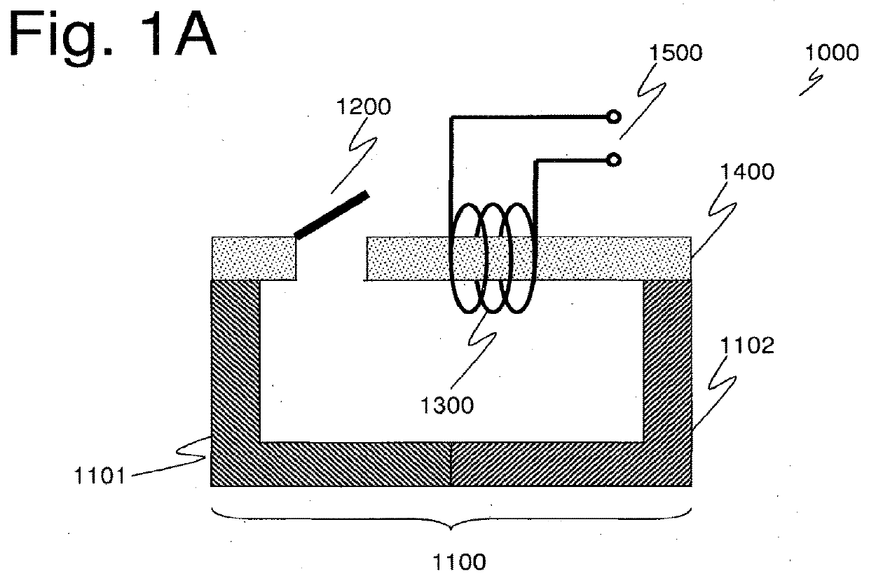
[0055]As can be seen in FIG. 1A, a wasted heat harvesting device 1000 in accordance with an embodiment of the present invention comprises a magnet 1100 including south pole 1101 and north pole 1102, a ferromagnet 1400, a switch 1200 and a coil 1300. The two ends of the coil 1300 act as a power output 1500 of the wasted heat harvesting device.

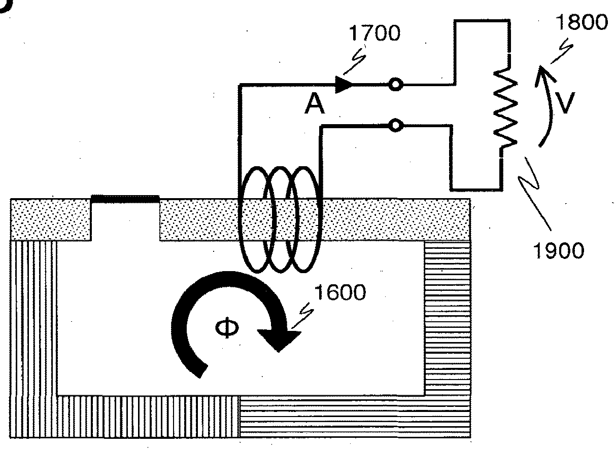
[0056]As can be seen in FIG. 1B, when the switch 1200 switches from the open position of FIG. 1A to the closed position of FIG. 1B, a magnetic flux Φ1600 is generated by the magnetic field of magnet 1500 being redirected through the ferromagnet 1400. The magnetic flux 1600 induces a current A 1700 in coil 1300. The current 1700 can be collected at power output 1500, for instance, to power a load 1900 resulting in a voltage drop V 1800.

[0057]In other words, the magnetic field is conveyed from a first region outside the coil 1300 to a second region inside the coil 1300 by the switch 1200.

[0058]Symmetrically, when the switch moves from the closed p...


PUM

PropertyMeasurementUnit
thickaaaaaaaaaa
thickaaaaaaaaaa
thickness T1aaaaaaaaaa

Abstract

A wasted heat harvesting device for harvesting electricity including switching means configured to convey a magnetic field from a first region to at least a second region when the temperature of the switching means crosses a predetermined temperature.

Description

CROSS-REFERENCE TO RELATED APPLICATIONS[0001]This application is a continuation of U.S. patent application Ser. No. 14 / 233,685, filed Jan. 17, 2014, which was a national phase entry under 35 U.S.C. § 371 of International Patent Application PCT / IB2012 / 001415, filed Jul. 20, 2012, designating the United States of America and published in English as International Patent Publication WO 2013 / 014511 A1 on Jan. 31, 2013, which claims the benefit under Article 8 of the Patent Cooperation Treaty and under 35 U.S.C. § 119(e) to French Patent Application Serial No. 1156837, filed Jul. 26, 2011, the disclosure of each of which is hereby incorporated herein in its entirety by this reference.BACKGROUND[0002]In recent years, the development of renewable energy has increased due to concern over the availability of fossil energy sources as well as environmental concerns. Among the different kinds of renewable energy sources, solar energy is the most abundant. Accordingly, there has been intensive re...

Claims


Application Information

Patent Timeline
Patent Type & Authority Applications(United States)
IPC IPC(8): H02N11/00H02S40/44H01F41/14H01L31/052H01L37/04
CPCY02E10/50H02S40/44H01F41/14Y10T29/4902H01L31/052H02N11/002H01L37/04Y02E10/60H10N15/20H01L31/053H10N50/80H10N50/85
Inventor KRAUSE, RAINERGHYSELEN, BRUNO
Owner SAINT AUGUSTIN CANADA ELECTRIC
Why Eureka
Try Eureka