
Fuel cell
a fuel cell and cell technology, applied in the field of fuel cells, can solve problems such as unstable voltage of the fuel cell, and achieve the effect of reducing or eliminating the variation in pressure loss
- Summary
- Abstract
- Description
- Claims
- Application Information
AI Technical Summary
Benefits of technology
Problems solved by technology
Method used
Image

Examples
embodiment
A. Embodiment
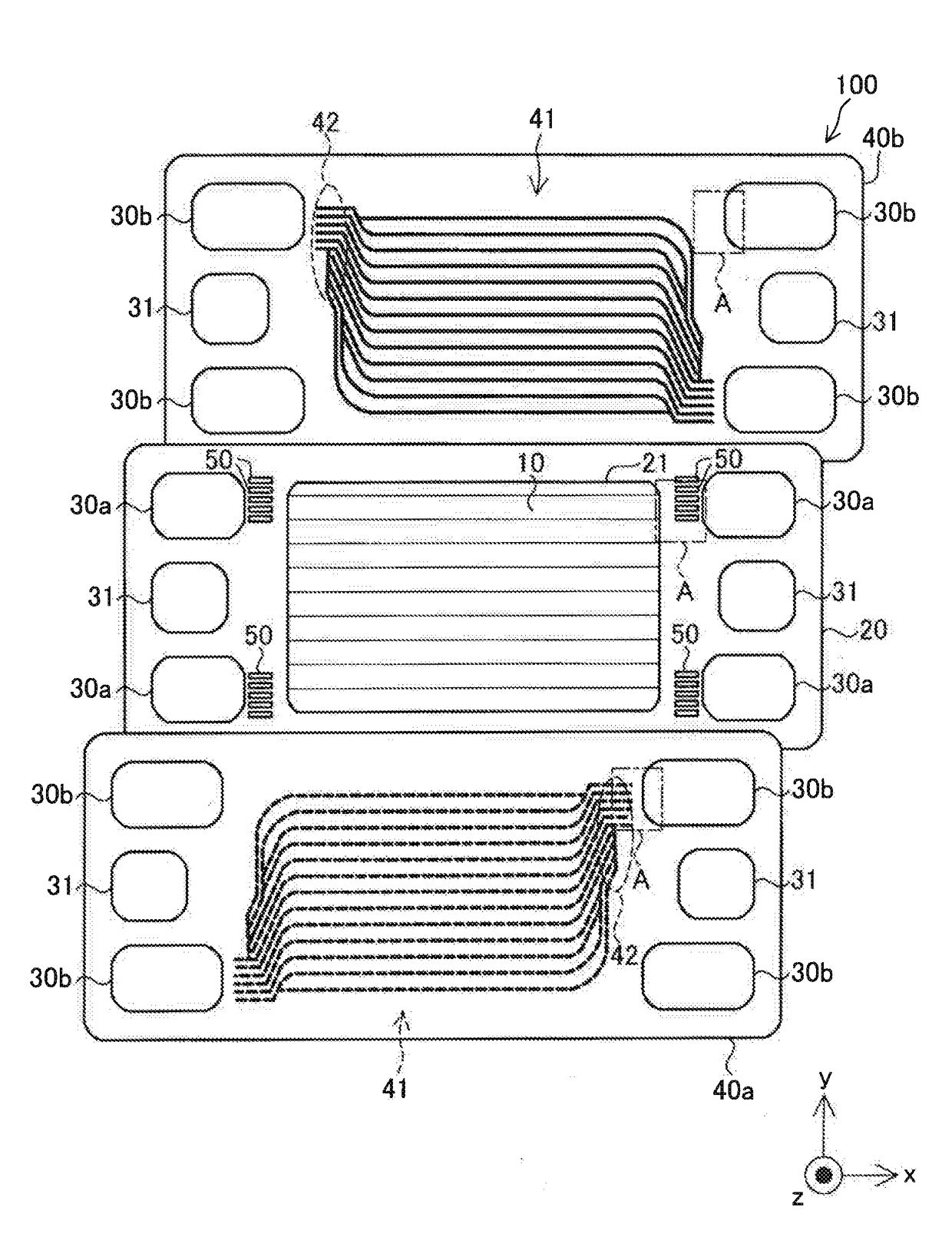
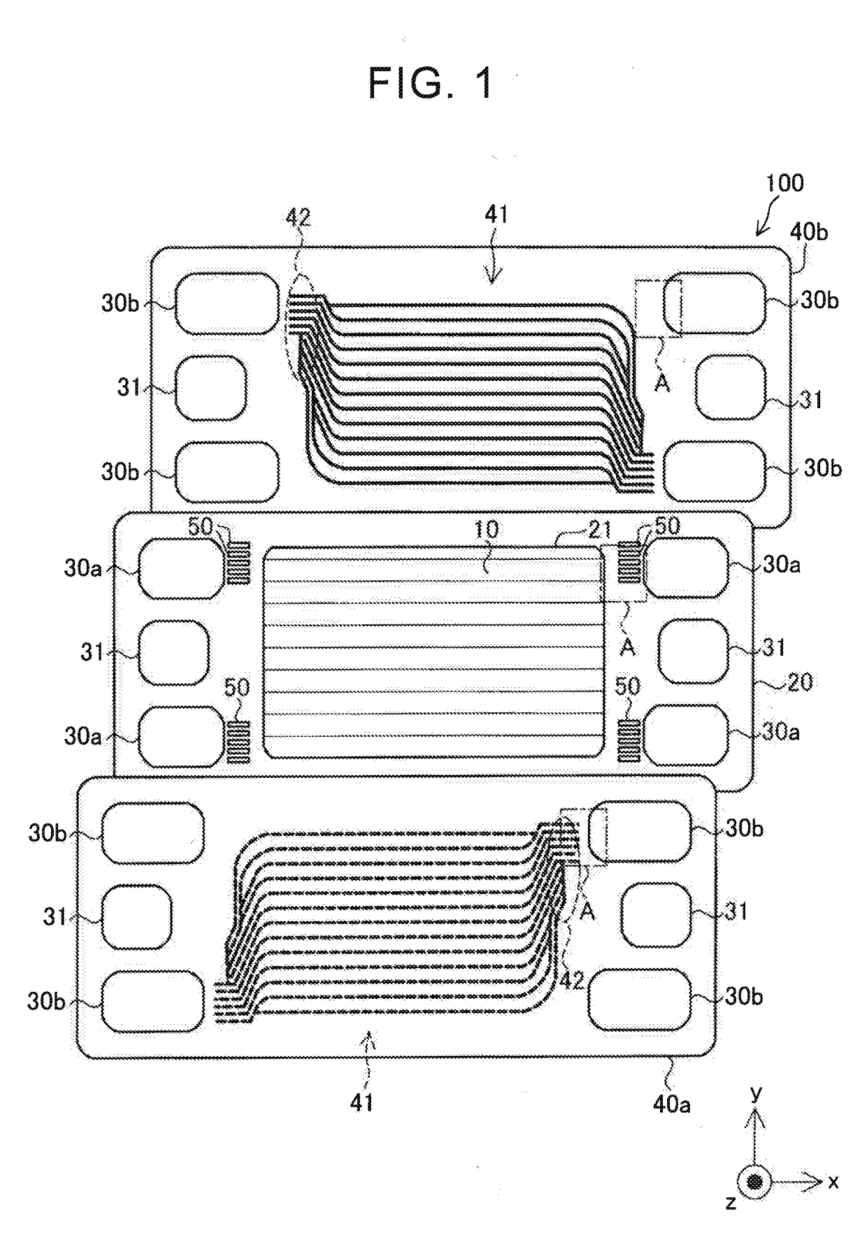
[0020]FIG. 1 is an explanatory exploded view of a fuel cell 100 according to one embodiment of the disclosure. The fuel cell 100 is a polymer electrolyte fuel cell that is supplied with hydrogen and oxygen as reaction gases, and generates electric power. The fuel cell 100 includes a power generating body 10, a resin frame 20, a pair of separators 40a, 40b, coolant manifolds 31, flow channels 41, and distribution flow channels 42.
[0021]The power generating body 10 includes an electrolyte membrane (not shown), catalyst layers (not shown) formed adjacent to the opposite surfaces of the electrolyte membrane, and gas diffusion layers (not shown). The electrolyte membrane is a solid polymer thin film that shows good protonic conductivity when it is in a wet state. The electrolyte membrane is provided by an ion-exchange membrane of fluorine-based resin, for example. The catalyst layer includes a catalyst that promotes chemical reaction between hydrogen and oxygen, and carbon p...
first modified example
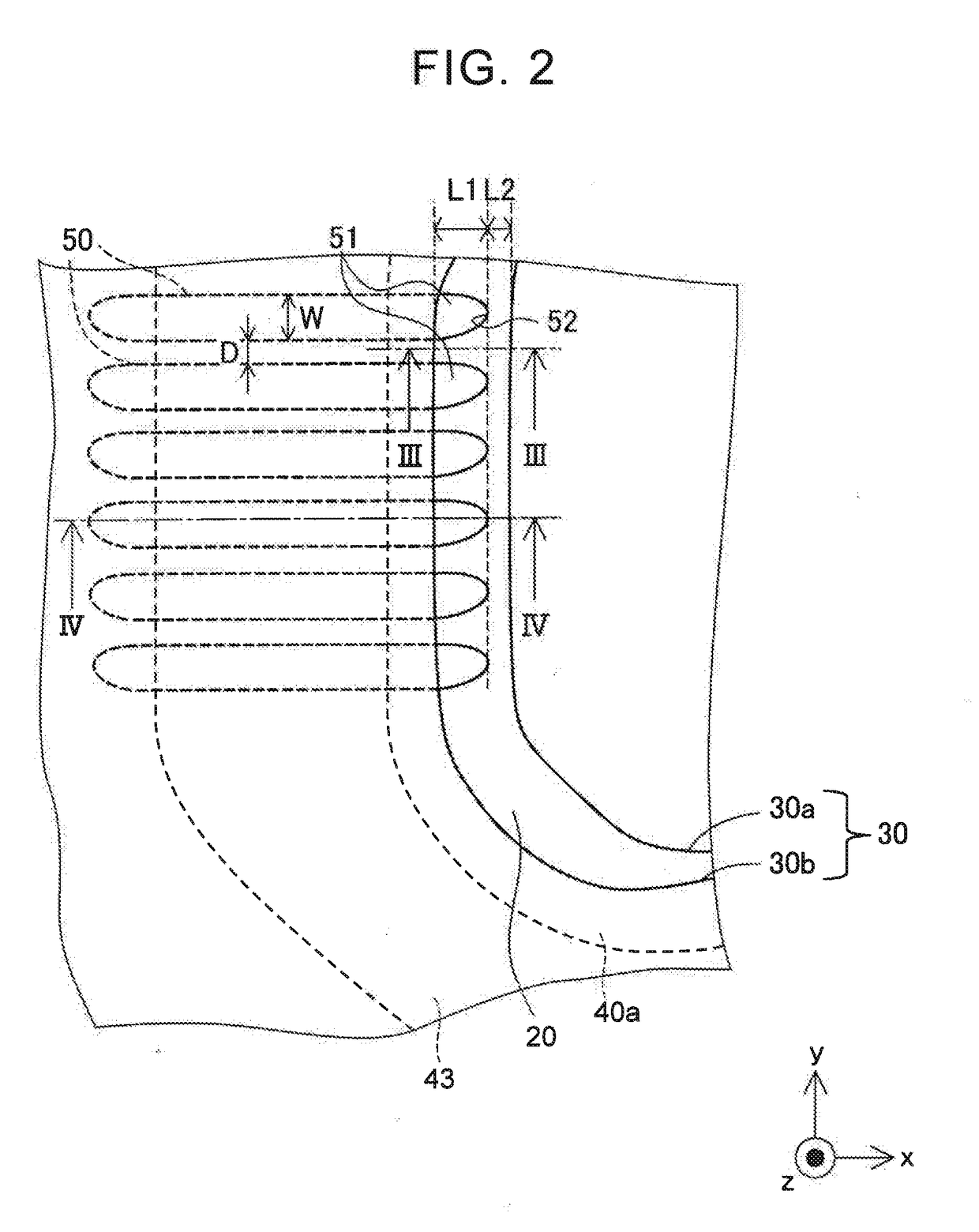
[0040]FIG. 7 is an enlarged view of a first modified example corresponding to the enlarged view (FIG. 2) of the “A” portion, which illustrates the case where the resin frame 20 and the pair of separators 40 of FIG. 1 are joined together. In the illustrated embodiment, the gas introduction channels 50 are formed in parallel with each other, when viewed in the direction (z-axis direction) of lamination of the separators 40 on the resin frame 20. On the other hand, as shown in FIG. 7, the gas introduction channels 50 may be formed such that some of the channels 50 are arranged in a fan-like form against the manifolds 30.
second modified example
[0041]In the illustrated embodiment, the resin frame 20 has a plurality of gas introduction channels 50, and the length L1 of all of the gas introduction parts 51 is the same length. On the other hand, the gas introduction parts 51 of some of the gas introduction channels 50 may have a different length or lengths.
PUM
| Property | Measurement | Unit |
|---|---|---|
| length | aaaaa | aaaaa |
| voltage | aaaaa | aaaaa |
| pressure loss | aaaaa | aaaaa |
Abstract
Description
Claims
Application Information