Fuel cell

a fuel cell and cell technology, applied in the field of fuel cells, can solve problems such as unstable voltage of the fuel cell, and achieve the effect of reducing or eliminating the variation in pressure loss

Active Publication Date: 2020-11-03
TOYOTA JIDOSHA KK
View PDF5 Cites 0 Cited by
  • Summary
  • Abstract
  • Description
  • Claims
  • Application Information

AI Technical Summary

Benefits of technology

[0004]For example, in JP 2014-063727 A, when a through-hole is formed in a resin frame within a range in which the frame is sandwiched between separators, to form a gas introduction channel, as shown in FIG. 6, an inlet through which reaction gas is introduced may be closed or blocked, as shown in the lower section of FIG. 6, if the position of the resin frame relative to the separators is shifted due to a manufacturing error, for example. Therefore, variations may arise in a pressure loss that appears when reaction gas is led to the membrane electrode assembly, and the voltage of the fuel cell may become unstable. Thus, a technology that can reduce or eliminate the variation in the pressure loss at the time of introduction of reaction gas into the fuel cell has been desired.
[0005]One aspect of the disclosure is concerned with a fuel cell having a power generating body including a membrane electrode assembly, a resin frame placed around the power generating body, and a pair of separators laminated on the resin frame so as to sandwich the power generating body and the resin frame. The resin frame has a resin-frame-side manifold in which reaction gas flows in a direction passing through the resin frame, an opening that holds the power generating body, and a gas introduction channel formed through the resin frame between the resin-frame-side manifold and the opening. The pair of separators has a separator-side manifold through which the reaction gas flows, and the separator-side manifold is provided at a position corresponding to the resin-frame-side manifold as viewed in a lamination direction. The gas introduction channel has a gas introduction part that extends into the separator-side manifold, when viewed in the lamination direction. In the fuel cell thus constructed, the gas introduction channel formed in the resin frame extends into the separator-side manifold. Therefore, even when the position of the resin frame relative to the separators is shifted due to a manufacturing error, for example, an inlet through which reaction gas is introduced can be prevented from being closed or blocked. Accordingly, variation in a pressure loss at the time of introduction of reaction gas into the fuel cell can be reduced or eliminated.
[0006]At least one of the pair of separators may have a recessed portion at a position facing the gas introduction channel, and the length of the recessed portion along a direction of gas flow in the gas introduction channel may be shorter than the length of the gas introduction channel. In the fuel cell thus constructed, the total thickness of a plurality of fuel cells stacked together can be reduced by an amount corresponding to the thickness of the recessed portions; therefore, the thickness can be prevented from being excessively increased.
[0007]The resin frame may have a plurality of gas introduction channels between the resin-frame-side manifold and the opening, and each of the plurality of gas introduction channels may be the above-indicated gas introduction channel of the resin frame. The gas introduction parts of at least a part of the plurality of gas introduction channels may have substantially the same length. With the fuel cell thus constructed, variation in the pressure loss among the gas introduction channels can be reduced or eliminated.
[0008]In the fuel cell as described above, a plurality of flow channels that permit the reaction gas to flow into the power generating body may be connected with the gas introduction channel, between the pair of separators and the resin frame, and the pair of separators may have a distribution flow channel that distributes the reaction gas supplied from the gas introduction channel to the flow channels. With the fuel cell thus constructed, the reaction gas introduced from the gas introduction channel can be distributed to a larger number of flow channels; therefore, the power generation efficiency can be improved.

Problems solved by technology

Therefore, variations may arise in a pressure loss that appears when reaction gas is led to the membrane electrode assembly, and the voltage of the fuel cell may become unstable.

Method used


Image

  • Fuel cell
  • Fuel cell
  • Fuel cell

Examples


embodiment

A. Embodiment

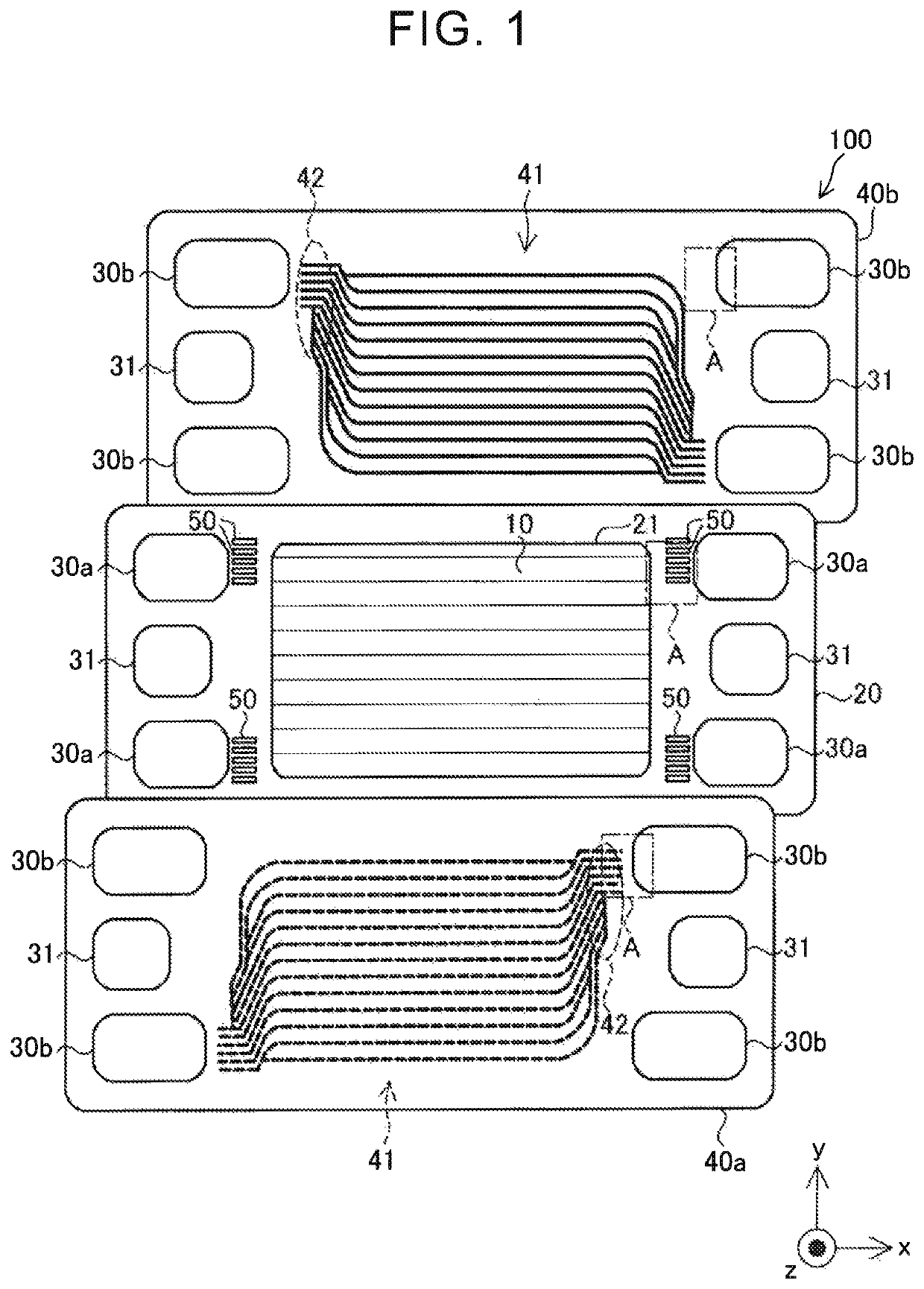
[0020]FIG. 1 is an explanatory exploded view of a fuel cell 100 according to one embodiment of the disclosure. The fuel cell 100 is a polymer electrolyte fuel cell that is supplied with hydrogen and oxygen as reaction gases, and generates electric power. The fuel cell 100 includes a power generating body 10, a resin frame 20, a pair of separators 40a, 40b, coolant manifolds 31, flow channels 41, and distribution flow channels 42.

[0021]The power generating body 10 includes an electrolyte membrane (not shown), catalyst layers (not shown) formed adjacent to the opposite surfaces of the electrolyte membrane, and gas diffusion layers (not shown). The electrolyte membrane is a solid polymer thin film that shows good protonic conductivity when it is in a wet state. The electrolyte membrane is provided by an ion-exchange membrane of fluorine-based resin, for example. The catalyst layer includes a catalyst that promotes chemical reaction between hydrogen and oxygen, and carbon p...

first modified example

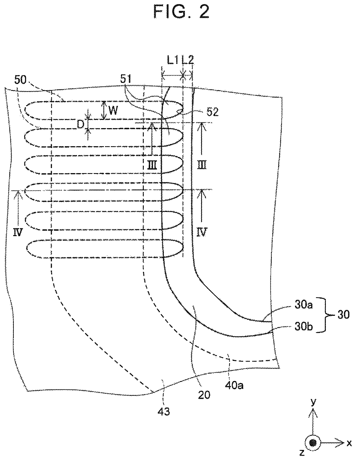
[0040]FIG. 7 is an enlarged view of a first modified example corresponding to the enlarged view (FIG. 2) of the “A” portion, which illustrates the case where the resin frame 20 and the pair of separators 40 of FIG. 1 are joined together. In the illustrated embodiment, the gas introduction channels 50 are formed in parallel with each other, when viewed in the direction (z-axis direction) of lamination of the separators 40 on the resin frame 20. On the other hand, as shown in FIG. 7, the gas introduction channels 50 may be formed such that some of the channels 50 are arranged in a fan-like form against the manifolds 30.

second modified example

[0041]In the illustrated embodiment, the resin frame 20 has a plurality of gas introduction channels 50, and the length L1 of all of the gas introduction parts 51 is the same length. On the other hand, the gas introduction parts 51 of some of the gas introduction channels 50 may have a different length or lengths.


PUM

PropertyMeasurementUnit
opening areaaaaaaaaaaa
areaaaaaaaaaaa
lengthaaaaaaaaaa

Abstract

A fuel cell includes a power generating body including a membrane electrode assembly, a resin frame placed around the power generating body, and a pair of separators laminated on the resin frame so as to sandwich the power generating body and the resin frame. The resin frame has a resin-frame-side manifold in which reaction gas flows in a direction passing through the resin frame, an opening that holds the power generating body, and a gas introduction channel formed through the resin frame between the resin-frame-side manifold and the opening. Each separator has a separator-side manifold through which the reaction gas flows, and which is provided at a position corresponding to the resin-frame-side manifold in a lamination direction, and the gas introduction channel has a gas introduction part that extends into the separator-side manifold, when viewed in the lamination direction.

Description

INCORPORATION BY REFERENCE[0001]The disclosure of Japanese Patent Application No. 2017-081042 filed on Apr. 17, 2017 including the specification, drawings and abstract is incorporated herein by reference in its entirety.BACKGROUND1. Technical Field[0002]The disclosure relates to a fuel cell.2. Description of Related Art[0003]A fuel cell having a resin frame that is placed at the outer periphery of a membrane electrode assembly, and is sandwiched between a pair of separators, is known (see Japanese Patent Application Publication No. 2014-063727 (JP 2014-063727 A)).SUMMARY[0004]For example, in JP 2014-063727 A, when a through-hole is formed in a resin frame within a range in which the frame is sandwiched between separators, to form a gas introduction channel, as shown in FIG. 6, an inlet through which reaction gas is introduced may be closed or blocked, as shown in the lower section of FIG. 6, if the position of the resin frame relative to the separators is shifted due to a manufactur...

Claims


Application Information

Patent Timeline
Patent Type & Authority Patents(United States)
IPC IPC(8): H01M8/1004H01M8/1007H01M8/0273H01M8/0258H01M8/2483H01M8/0267H01M8/242H01M8/0247
CPCH01M8/1004H01M8/0258H01M8/242H01M8/0247H01M8/0273H01M8/2483H01M8/1007H01M8/0267H01M8/0289Y02E60/50H01M8/0297H01M8/02H01M8/0271H01M8/10
Inventor SATO, KENJIOKADA, SACHIOKADONO, HIDEYA
Owner TOYOTA JIDOSHA KK
Why Eureka
Try Eureka