Cutting device

a cutting device and cutting plate technology, applied in the field of cutting plates, can solve the problems of uneven operation of the fastening position of the operation lever, insufficient the inability to achieve the flatness etc. of the upper surface of the base, etc., and achieve the effect of improving the operability of the operating lever and the usability of the cutting devi

Active Publication Date: 2016-05-31
MAKITA CORP
View PDF11 Cites 0 Cited by
  • Summary
  • Abstract
  • Description
  • Claims
  • Application Information

AI Technical Summary

Benefits of technology

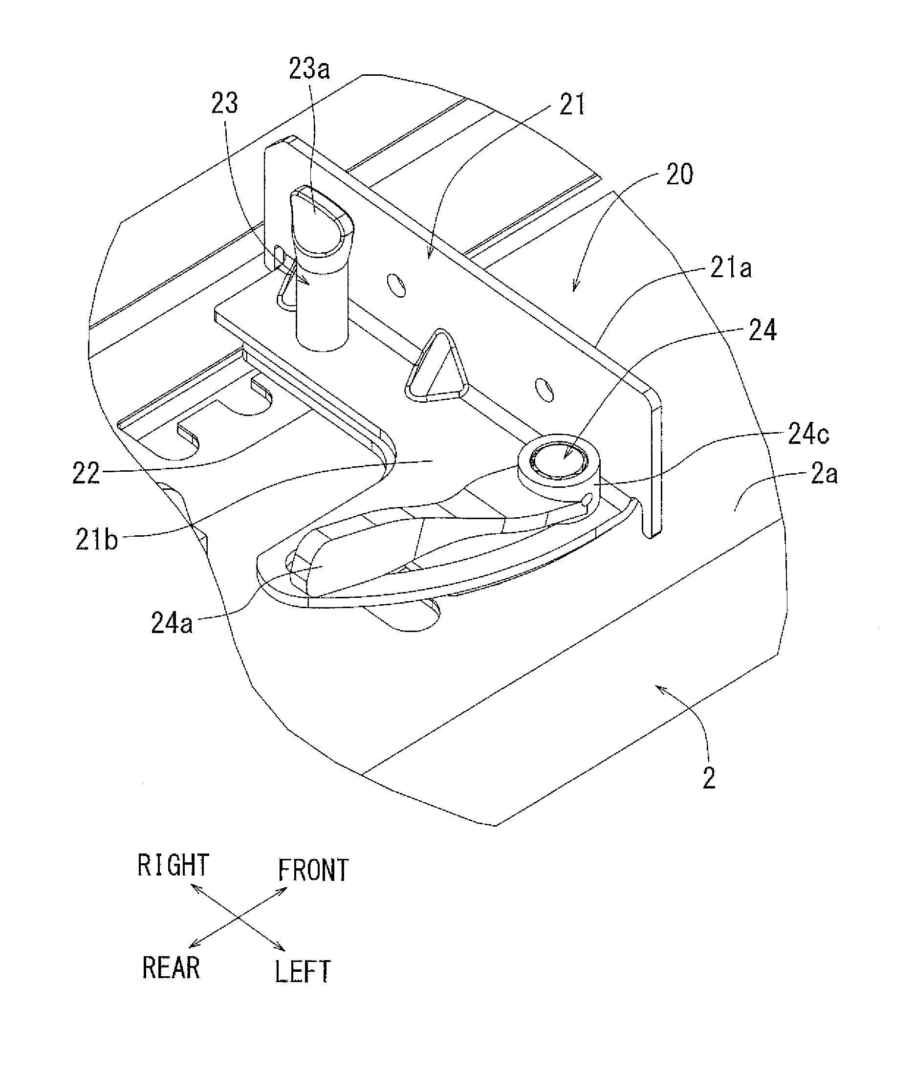
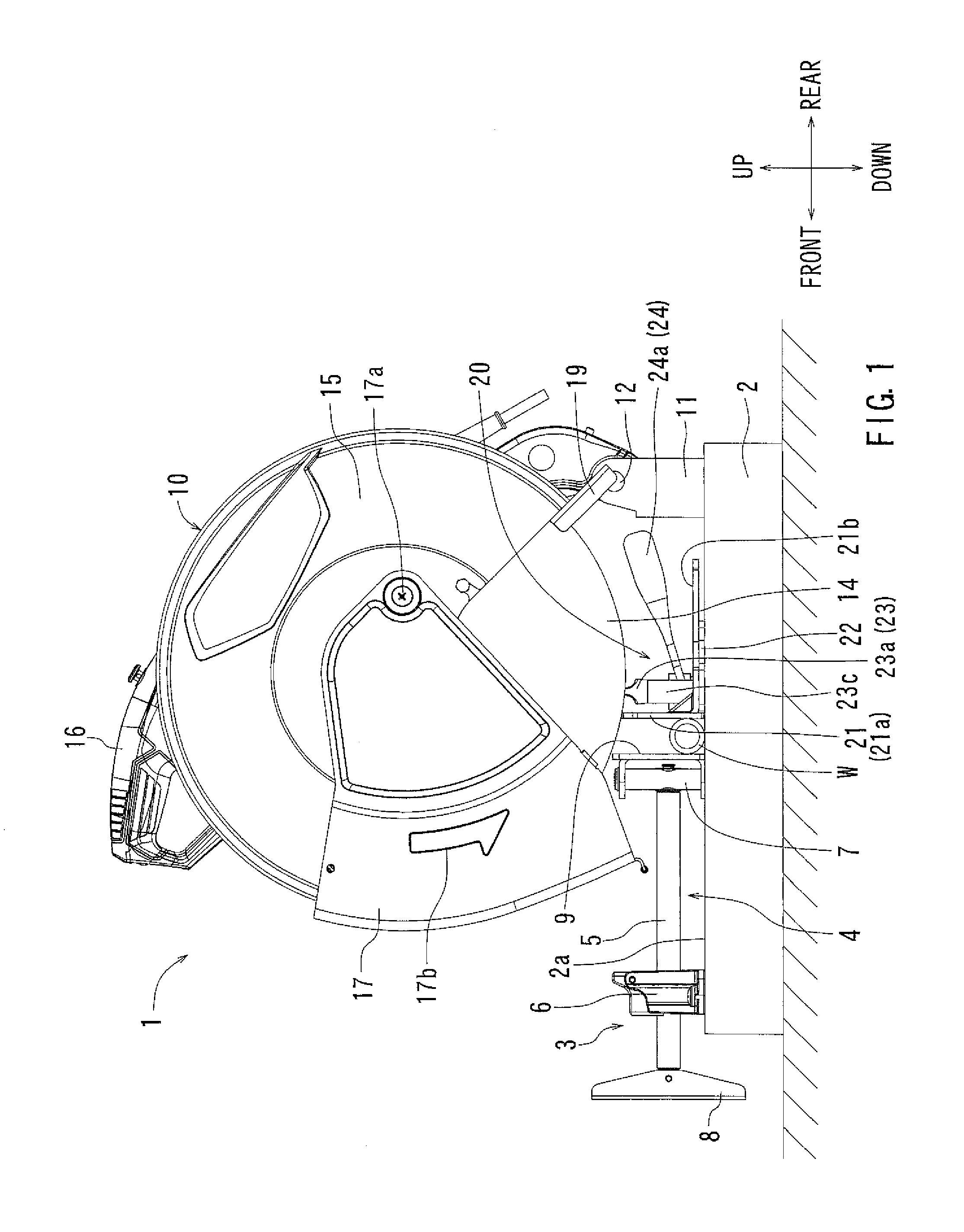
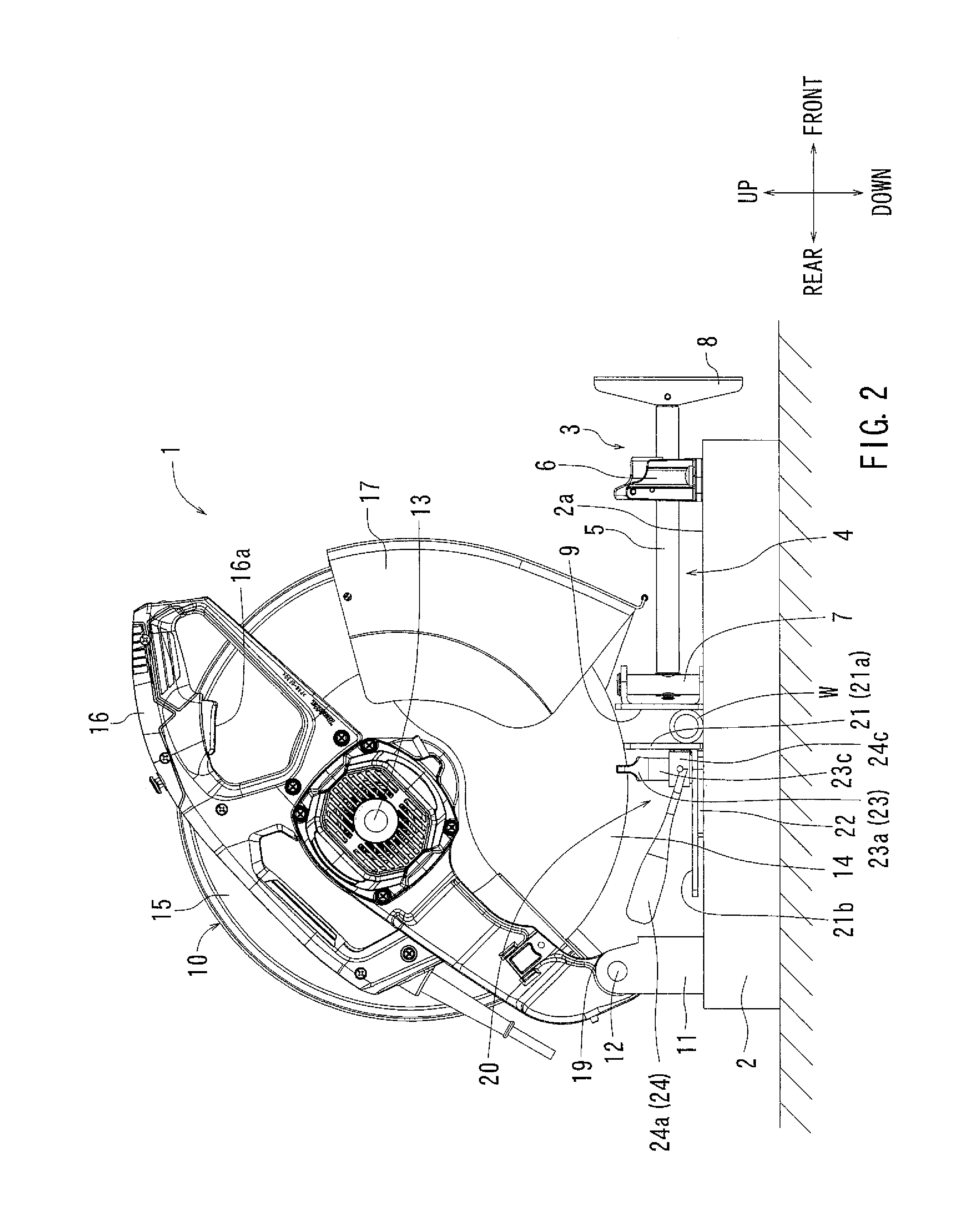
[0011]In the first aspect, the fence is configured to move upon the interposing member by loosening the second fixing member. Thus, even when the top plate part of the base has been warped, deflected, or undulated, the variation of an operating amount of the second fixing member can be reduced or eliminated. Because of this, operability and usability of the fence, and eventually of the cutting device can be improved.
[0017]In the above aspect, a positioning of the interposing member, and eventually of the fence in the front and rear directions may be rapidly performed with improved repeatability. In this respect, operability and usability of the fence, and eventually of the cutting device may be further improved.
[0021]In the above aspect, the engaging member can be forcibly inserted into a transverse groove hole by a biasing force of the biasing member. Because of this, operability may be further improved with respect to a positioning of the interposing member and the fence.

Problems solved by technology

Because of this, sufficient accuracy in flatness etc. of the upper surface of the base is not necessarily obtained due to welding strains etc.
As a result, in the case that a position of the fence is changed by applying the above-described tool-less structure to the base made of metal sheet parts, unevenness in a fastening position of the operation lever may occur.
In this way, there has been a problem that the operability of the operational lever and usability of the cutting device may be worsened.

Method used


Image

  • Cutting device
  • Cutting device
  • Cutting device

Examples


Embodiment Construction

[0041]Each of the additional features and teachings disclosed above and below may be utilized separately or in conjunction with other features and teachings to provide an improved cutting device. Representative examples of the present teaching, which examples utilize many of these additional features and teachings both separately and in conjunction with one another, will now be described in detail with reference to the attached drawings. This detailed description is merely intended to teach a person of skill in the art further details for practicing preferred aspects of the present teachings and is not intended to limit the scope of the invention. Only the claims define the scope of the claimed invention. Therefore, combinations of features and steps disclosed in the following detailed description may not be necessary to practice the invention in the broadest sense, and are instead taught merely to particularly describe representative examples of the invention. Moreover, various fea...


PUM

PropertyMeasurementUnit
angleaaaaaaaaaa
flatnessaaaaaaaaaa
biasing forceaaaaaaaaaa

Abstract

An interposing member is interposed between a base part of the fence plate and a top plate part of a base, and a position of the fence plate is changed on the interposing member. Because of this, deflection etc. of the top plate can be reduced and variation of an operating angle of an operating lever can be reduced when fixing the fence plate to the base.

Description

[0001]This application claims priority to Japanese patent application serial number 2013-226932, the contents of which are incorporated herein by reference.BACKGROUND OF THE INVENTION[0002]1. Field of the Invention[0003]Embodiments of the present invention relate to a cutting device mainly for metal machining. In more detail, they relate to a metal cutting chop saw for cutting material as a metal pipe etc.[0004]2. Description of the Related Art[0005]A cutting device for metal machining has an electric motor serving as a drive source, a circular grinding wheel or a chip saw serving as a cutting blade, a base on which a material to be cut is placed, and a tool main body that is vertically movable above the base and supported by the base. Further, the cutting device has a vise device for fixing a material to be cut on an upper surface of the base (a mounting surface of a material to be cut). A cutting device relating to the above is described in Japanese Laid-Open Patent Application No...

Claims


Application Information

Patent Timeline
Patent Type & Authority Patents(United States)
IPC IPC(8): B27B27/04B27B29/02B23D45/04B23D45/12B23D47/06
CPCB27B27/04B23D45/042B23D45/12B23D47/06B27B29/02Y10T83/7487Y10T83/758
Inventor KIMURA, YOSHIHIROAOYAMA, SYUJI
Owner MAKITA CORP
Why Eureka
Try Eureka