Multiple stage pump with multiple external control valves

a control valve and multi-stage technology, applied in the direction of positive displacement liquid engines, machines/engines, anti-theft devices, etc., can solve the problems of variable pump systems that are not currently or widely used in the automotive industry, the pump displacement of the hydraulic pump is not adjusted to the needed amount of energy, and the injection variation is not widely used

Inactive Publication Date: 2004-02-05
SIEMENS DIESEL SYST TECH
View PDF13 Cites 0 Cited by
  • Summary
  • Abstract
  • Description
  • Claims
  • Application Information

AI Technical Summary

Benefits of technology

[0010] A still further object of the present invention is to eliminate or reduce pressure peaks throughout the stages of the multiple stage pump.
[0011] Another object of the present invention is to reduce or eliminate injection variation in a fuel injector.
[0013] Also another object of the present invention is to provide both the rail and the pump sites of a multistage pump with a smooth pressure profile during the transient phase from stage to stage and during different volumes.
[0014] A further object of the present invention is to provide a more stable rail volume drop in a two stage pump system.

Problems solved by technology

In current systems, pump displacement of the hydraulic pump is not adjusted to the needed amount of energy for a desired application.
This is mainly due to cost constraints associated with manufacturing and designing variable pump displacement systems.
Thus, variable pump systems are not currently or widely used in the automotive industry due to these cost constraints.
Thus, the pump side must handle the additional load and will have a problem with the resultant durability.
Also, with these systems, on the rail side, the pressure peaks change the rail dynamic which, in turn, causes injection variations.

Method used


Image

  • Multiple stage pump with multiple external control valves
  • Multiple stage pump with multiple external control valves
  • Multiple stage pump with multiple external control valves

Examples


Embodiment Construction

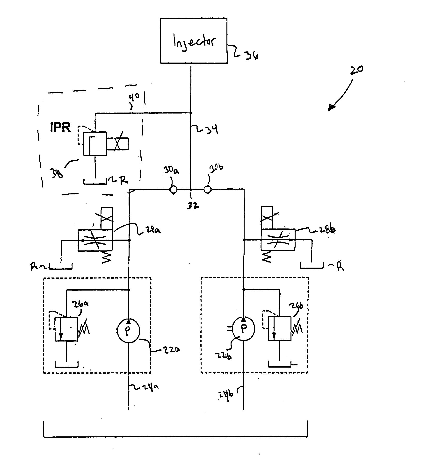
[0025] The present invention is directed to a multiple stage pump for hydraulic systems, and more particularly a rail and pump system adapted for providing working fluid to hydraulically controlled fuel injectors. The multiple stage pump of the present invention provides an adjustable system which increases fuel efficiency and reduces or eliminates pressure peaks throughout the stages of the multiple stage pump. The multiple stage pump of the present invention is also capable of reducing or eliminating injection variations in a fuel injector.

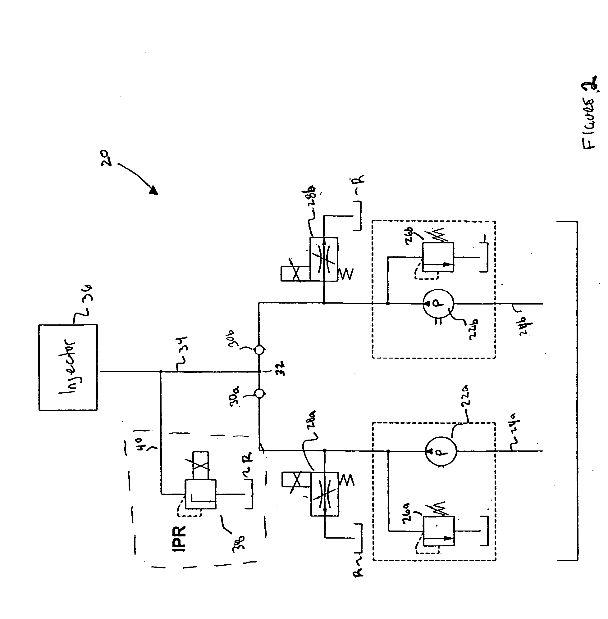
[0026] Referring now to FIG. 2, a first embodiment of the multiple stage pump is provided. In this embodiment, the multiple stage pump is generally depicted as reference numeral 20 and includes pumps 22a and 22b located on respective branches 24a and 24b of the multiple stage pump system 20 of the present invention. The pumps 22a, 22b are preferably arranged in parallel, and may be associated with respective valve and reservoir systems 26a, 26b....


PUM


Abstract

A multiple stage pump having valves upstream from each respective pump in a same line thereof. The respective lines then merge into a common line. The multiple stage pump prevents pressure variations and shot to shot fuel variations.

Description

[0001] The present application claims priority to U.S. provisional application serial No. 60 / 283,629, filed on Apr. 16, 2001, the entire disclosure which is incorporated herein by reference.[0002] 1. Field of the Invention[0003] The present invention generally relates to a multiple stage pump and, more particularly, to a variable displacement multiple stage pump for a hydraulic system.[0004] 2. BACKGROUND DESCRIPTION[0005] Hydraulic pumps are widely used in a vast array of automotive and heavy machinery applications. These applications may include, for example, drive vehicles, powerful hydraulic cylinders and injection systems. In current systems, pump displacement of the hydraulic pump is not adjusted to the needed amount of energy for a desired application. That is, the pump displacement is kept constant. This is mainly due to cost constraints associated with manufacturing and designing variable pump displacement systems. Thus, variable pump systems are not currently or widely use...

Claims


Application Information

Patent Timeline
Patent Type & Authority Applications(United States)
IPC IPC(8): F02M59/08F02M59/36F02M63/02F04B23/06F04B49/24
CPCF02M59/08F02M59/366F04B49/24F04B23/06F02M63/0225
Inventor NIETHAMMER, BERND
Owner SIEMENS DIESEL SYST TECH
Why Eureka
Try Eureka