

Light source modulation circuit, light source modulation method, and projector apparatus
a technology of light source modulation and light source, applied in the direction of electrical equipment, electromagnetic transmission, close-range type systems, etc., can solve the problems of information transfer jitters according to the on/off modulation waveform, and achieve the effect of preventing the occurrence of jitters and stably performing information transfer
- Summary
- Abstract
- Description
- Claims
- Application Information
AI Technical Summary
Benefits of technology
Problems solved by technology
Method used
Image


Examples
first exemplary embodiment
[0020]Hereinbelow, a first exemplary embodiment will be described with reference to FIGS. 1 to 3.
1-1. Configuration
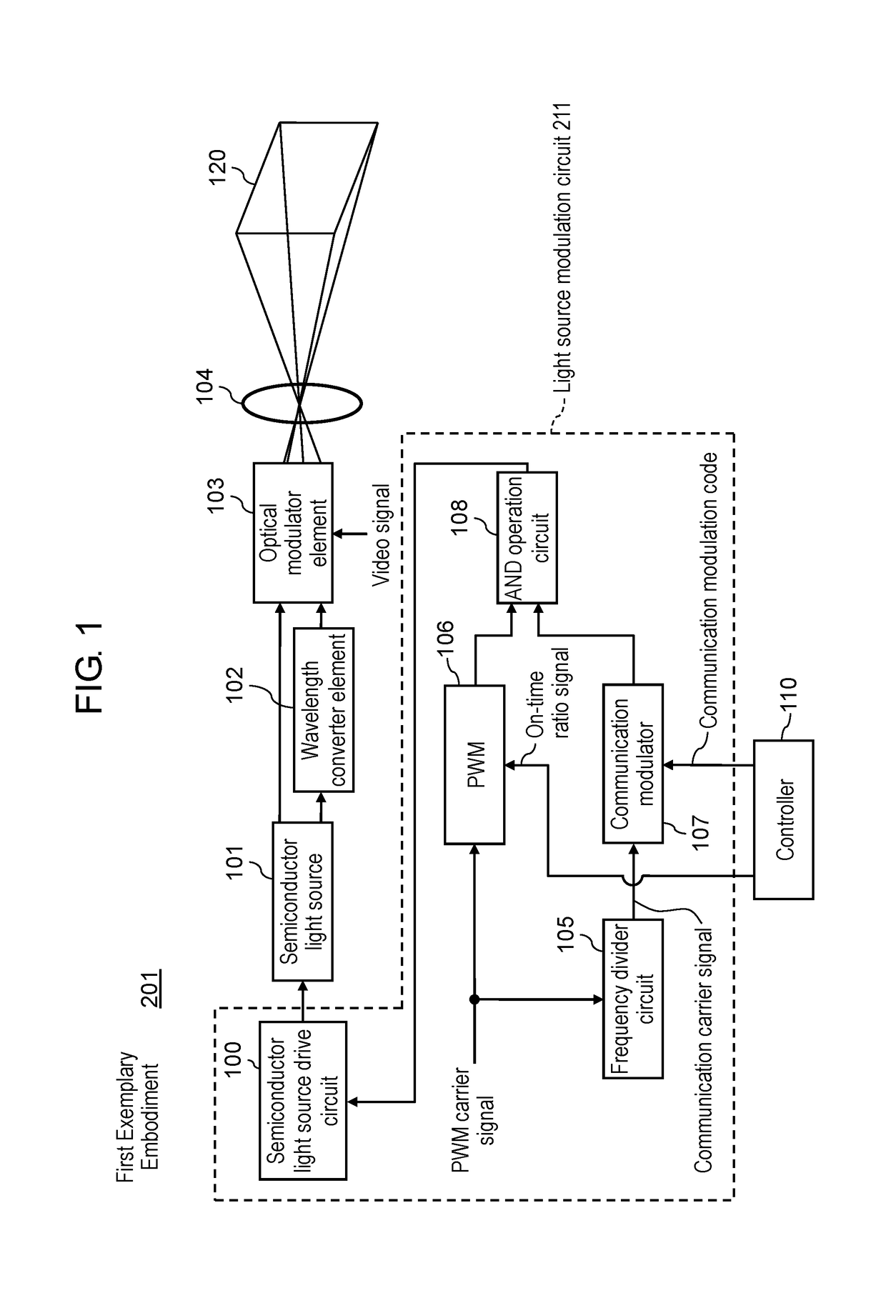
[0021]FIG. 1 is a block diagram illustrating an example of the configuration of projector apparatus 201 furnished with light source modulation circuit 211 according to the first exemplary embodiment. Referring to FIG. 1, projector apparatus 201 is furnished with light source modulation circuit 211, semiconductor light source 101, wavelength converter element 102, optical modulator element 103, projection lens 104, and controller 110. Here, light source modulation circuit 211 includes frequency divider circuit 105, pulse width modulator (PWM) 106, communication modulator 107, AND operation circuit 108, and semiconductor light source drive circuit 100.
[0022]Controller 110 controls the operations of projector apparatus 201 and generates a communication modulation code containing an on-time ratio signal for adjusting the brightness of semiconductor light source 101 and an i...
second exemplary embodiment
[0034]Hereinbelow, a second exemplary embodiment will be described with reference to FIGS. 4 and 5.
2-1. Configuration
[0035]FIG. 4 is a block diagram illustrating an example of the configuration of projector apparatus 202 furnished with light source modulation circuit 212 according to the second exemplary embodiment, and FIG. 5 is a timing chart of various signals, illustrating an example of the operations of light source modulation circuits 212 and 213 according to the second exemplary embodiment and the comparative example.
[0036]Referring to FIG. 4, when compared with light source modulation circuit 211 of FIG. 1, light source modulation circuit 212 according to the second exemplary embodiment is characterized by including multiplying circuit 109 in place of frequency divider circuit 105. In the following, differences will be detailed.
[0037]Referring to FIG. 4, multiplying circuit 109 multiplies a communication carrier signal by a predetermined multiplication number to generate a P...
PUM
 Abstract
Description
Claims
Application Information