Transmission concept using multi-user superposition coding

a transmission concept and superposition coding technology, applied in transmission, modulated carrier systems, channel estimation, etc., can solve the problems of.2&3 being particularly problematic, and achieve the effect of reducing the overhead of controlling and sending the phase shift compensation signal

Active Publication Date: 2019-06-06
FRAUNHOFER GESELLSCHAFT ZUR FOERDERUNG DER ANGEWANDTEN FORSCHUNG EV
View PDF0 Cites 4 Cited by
  • Summary
  • Abstract
  • Description
  • Claims
  • Application Information

AI Technical Summary

Benefits of technology

[0022]In order to reduce the control overhead caused by sending the phase shift and / or amplitude ratio compensation signals, one or both of them may be sent within messages of a first type and messages of a second type, with sending messages of first and second types in a differently frequent manner. In doing so, the messages of the first type, for example, could be sent less frequently but in a manner allowing for signaling phase offset not representable by the respective signal within the messages of the second type. A similar effect could be achieved by providing messages with an indicator field changing the way another field is read, such as a phase shift field in case of a phase shift compensation signal or a power control field in case of an amplitude ratio compensation signal.
[0023]In accordance with a further embodiment, the phase shift compensation is attained by the phase shift compensation signal in a successive manner by indicating a phase shift to be taken into account in the next task of mapping data onto the respective transmitter's constellation relative to a current phase shift used by the recipient of the phase shift correction signal, i.e. the respective transmitter, when mapping data onto its constellation. By this manner, the overhead in sending the phase shift compensation signal is further reduced.

Problems solved by technology

However for uplink MUST (UL-MUST), the problem is to decode the received composite constellation at the BS formed by different UEs as depicted in FIG. 17a.
MUST-Cat.2&3 is especially problematic in view of the label-bit assignment on the composite constellation.

Method used


Image

  • Transmission concept using multi-user superposition coding
  • Transmission concept using multi-user superposition coding
  • Transmission concept using multi-user superposition coding

Examples


Embodiment Construction

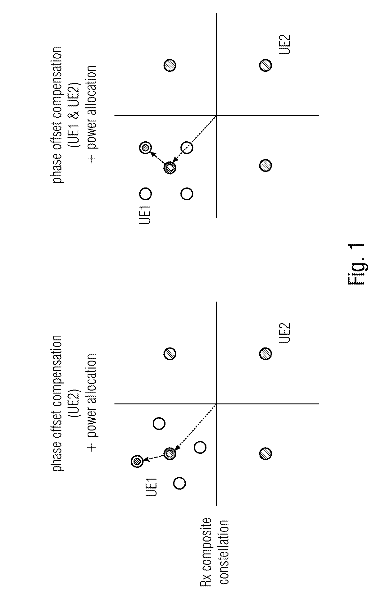
[0043]In order to motivate an easy understanding of the following description of embodiments of the present application, with respect to FIG. 1 the description in the introductory portion of the specification of the present application with respect to usage of multi-user superposition transmission in downlink scenarios and the problems associated with seeking to transfer this transmission concept to uplink is resumed. Accordingly, the considerations set out for this motivation should not be treated as limiting with respect to the embodiments of the present application described subsequently.

[0044]In order to decode a MUST composite constellation, the receiver, i.e. the base station in uplink case or UEs in DL case, needs channel state estimation of participating UL-MUST UEs in case of UL-(uplink) MUST or of participating BSs from which the superimposing signals stem in case of DL (downlink) MUST, or interference coordination, in order to compensate for the mutual interference of the...


PUM


Abstract

The transmission of data signals transmitted by a plurality of transmitters may be rendered more efficient by combining multi-user superposition coding with appropriate phase shift estimation at the receiver so that phase shift compensation at the transmitter's side may lead to a superposition of the data signals which may be demapped correctly so as to obtain information data per data signal. Owing to the combination, the concept is applicable to typical uplink situations or downlink situations of separate contributing BSs: contrary to the simple downlink situation where the data signals stem from one BS and are superimposed in one domain, namely the base station's domain, the data signals to be superimposed stem from separate transmitters, such as user entities or mobile terminals in the typical uplink situation, or different base stations in the downlink situation.

Description

CROSS-REFERENCES TO RELATED APPLICATIONS[0001]This application is a continuation of copending International Application No. PCT / EP2017 / 070438, filed Aug. 11, 2017, which is incorporated herein by reference in its entirety, and additionally claims priority from European Application No. EP 16 183 897.4, filed Aug. 11, 2016, which is incorporated herein by reference in its entirety.[0002]The present application is concerned with a concept for transmission via multi-user superposition coding such as a transmission concept using multi-user superposition transmission (MUST).BACKGROUND OF THE INVENTION[0003]In downlink MUST, synchronization between the overlaid signals dedicated for different UEs can be simply ensured by the eNB. However for uplink MUST (UL-MUST), the problem is to decode the received composite constellation at the BS formed by different UEs as depicted in FIG. 17a. At the receiving BS, the component constellations from different UEs are effected by the independent channel...

Claims


Application Information

Patent Timeline
Patent Type & Authority Applications(United States)
IPC IPC(8): H04L5/00H04L27/26H04L25/02
CPCH04L5/0073H04L5/0037H04L27/2662H04L27/2621H04L25/0204H04L5/0051H04L27/0014H04L27/3411H04L27/3455H04L27/3488H04L27/367H04L2027/002
Inventor FEHRENBACH, THOMASGOEKTEPE, BARISHELLGE, CORNELIUSDOMMEL, JOHANNESTHIELE, LARS
Owner FRAUNHOFER GESELLSCHAFT ZUR FOERDERUNG DER ANGEWANDTEN FORSCHUNG EV
Why Eureka
Try Eureka