Illuminated decorative part

Active Publication Date: 2019-06-13
DAIMLER AG
View PDF1 Cites 7 Cited by
  • Summary
  • Abstract
  • Description
  • Claims
  • Application Information

AI Technical Summary

Benefits of technology

The patent is about a new invention of an illuminated decorative part that is very compact and can emit light with high contrast and brightness. The design of the part is easy to install and can be programmed to show different shapes and symbols. The part is made up of layers that can be very thin, and the space it takes up can be relatively small. The light is emitted by LEDs that are arranged in a matrix and can be controlled to produce different light effects. The new invention, such as a decorative stripe for the vehicle dashboard, can be installed easily and does not require complicated wiring. The illuminated decorative part can be used to create an optical effect that enhances the appearance of the vehicle interior.

Problems solved by technology

The design of the decorative lighting unit in the generic prior art has the disadvantage that, due to the lens and the inserted stripe image in the interior of the decorative lighting part, it requires a relatively large design in the direction of the light emission, i.e. substantially orthogonally to the surface facing the observer of the decorative lighting part.
This is disadvantageous for use, for example, in the area of a dashboard of a motor vehicle, since the available installation space here is typically very limited in the depth direction.
A further disadvantage consists in the fact that a stripe image is required in order to represent the desired display.
Typically, this stripe image is transilluminated in the manner of a transparent photo slide, which leads to a not insignificant loss of light, and which correspondingly limits the optical brilliance that can be achieved with the decorative lighting unit according to the generic prior art.
For example, it can consist of a sufficiently ductile material to ensure crash safety for use in a vehicle despite the use of the optically very high-grade PMMA, which alone would not provide any crash safety.

Method used


Image

  • Illuminated decorative part
  • Illuminated decorative part
  • Illuminated decorative part

Examples


Embodiment Construction

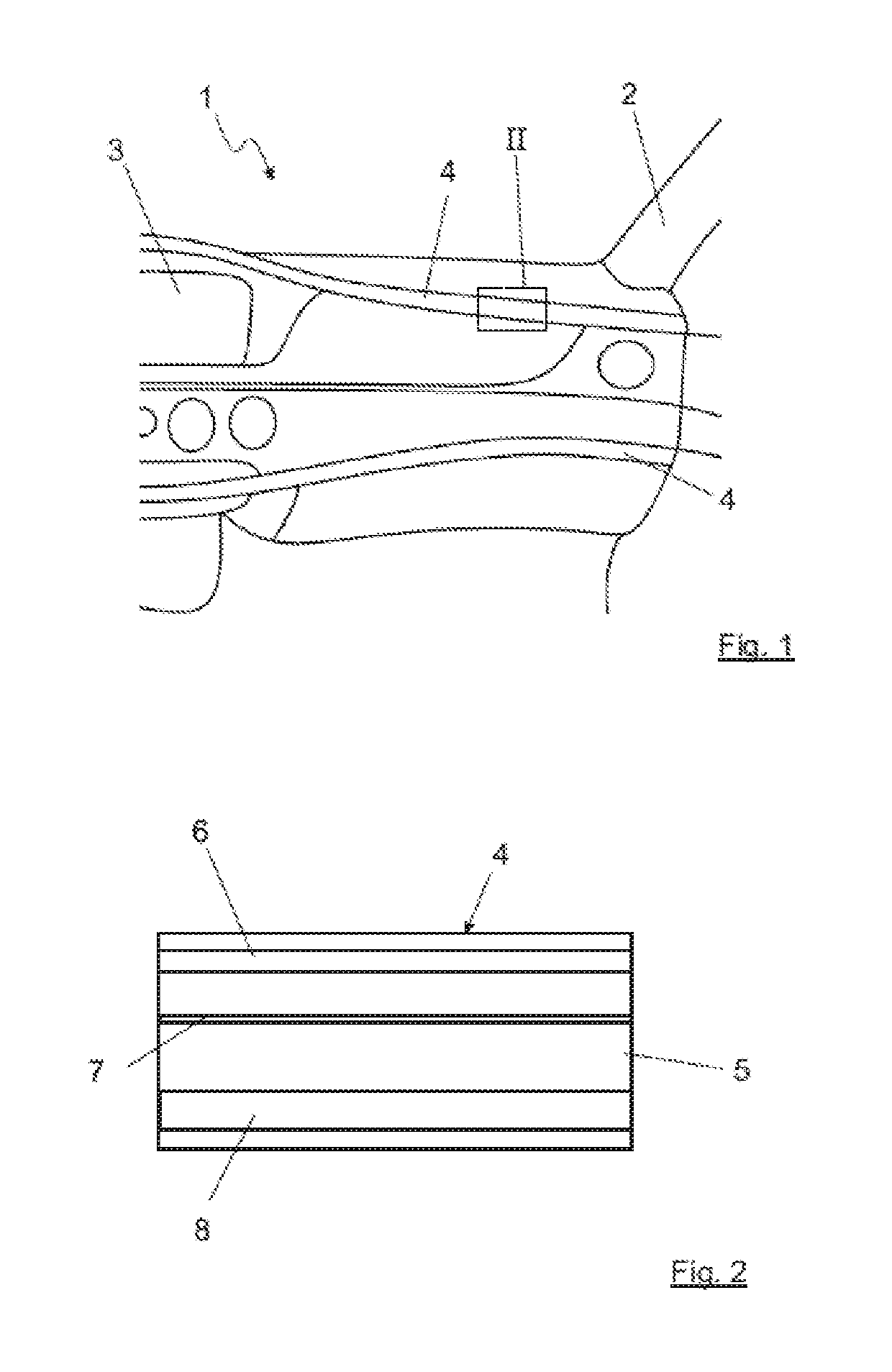
[0024]A section of a dashboard 1 of a vehicle, which is not shown in its entirety, can be discerned in the drawing in FIG. 1. This section substantially shows the region of the dashboard 1 in front of the so-called passenger seat between an exemplarily shown A-pillar 2 of the vehicle and a display 3, which can be discerned on the left edge of the image and which should be a part of the central console of the vehicle. Two exemplary illuminated decorative parts are arranged in the vicinity of the dashboard, each of which is identified with 4 and which are configured here as continuous decorative stripes running through the vehicle dashboard 1 transverse to the driving direction. These illuminated decorative parts 4, the structural details of whose design will be discussed later, are typically configured with a flat and thus lightly curved surface, which is normally convexly curved toward the observer. For the sake of simplification, the discussion that follows is of a flat surface, ev...


PUM


Abstract

An illuminated decorative part includes a flat visible side facing an observer and an illumination region behind the visible side as viewed by the observer, which has multiple discrete light sources. At least partially transparent optical elements that influence the light are arranged between the visible side and the illumination region. The optical elements include at least one flat scattering element. The decorative part includes light guides for guiding the light orthogonally to the surface of the visible side arranged between the scattering element and at least one—but not all—of the light sources.

Description

BACKGROUND AND SUMMARY OF THE INVENTION[0001]The invention relates to an illuminated decorative part.[0002]Illuminated decorative parts, in particular for adjustable ambient lighting within a vehicle, are known from the prior art. Patent DE 10 2009 030 684 A1 by the applicant relates to a decorative element of this type, which has a transparent top layer, into which light can be coupled. Corresponding cut-outs can then be provided in an applied decorative film in order to emit the light through them, in particular into the interior compartment of a vehicle that is equipped with the decorative element.[0003]An illuminated decorative part of the type in question is known by the term ‘decorative lighting unit’ from DE 10 2010 055 129 A1. The decorative lighting unit consists of a support that is provided with light sources, an optical element in the form of an optical lens, and a diffusor and a mask. A stripe image or another type of image display is inserted between the diffusor and t...

Claims


Application Information

Patent Timeline
IPC IPC(8): B60Q3/66B60Q3/54B60Q3/60B60Q3/14B60Q3/74
CPCB60Q2500/10B60R13/0256B60Q3/14B60Q3/74B60Q3/54B60Q3/60B60R2013/0287B60Q3/66B60Q3/64B60Q3/78B60Q2900/40
Inventor BETZ, CHRISTIANBETZ, DANIELBOROWSKI, MARTINMOSER, KEVIN
Owner DAIMLER AG
Why Eureka
Try Eureka