Box by Pin Perforating Gun System

a perforating gun and pin technology, applied in the direction of weapons, fluid removal, borehole/well accessories, etc., can solve the problems of short communication circuit, difficulty in maintaining close control of gun assembly/loading procedures, and failure of perforating guns or other tools to fire or function appropriately

Active Publication Date: 2019-06-27
HUNTING TITAN
View PDF0 Cites 56 Cited by
  • Summary
  • Abstract
  • Description
  • Claims
  • Application Information

AI Technical Summary

Benefits of technology

[0020]One embodiment to eliminate the need to make wire connections between perforating guns is to provide a receptacle or resilient connector that engages and maintains electrical contact as two perforating guns are threaded together.

Problems solved by technology

Because the service company shop often employs a single gun loader, maintaining close control on the gun assembly / loading procedures can become difficult.
When typical a perforating gun is assembled / loaded either at the well site or at a service company shop, there is risk of incorrect assembly or damage to electrical wiring or other components that may cause the perforating gun or other tools to fail to fire or fail to function appropriately.
For example, the threading of a pass-through wire through the gun body or charge holder presents numerous opportunities for the insulation of the wire to be stripped on sharp metal edges resulting in shorts in the communications circuit.
This requires time and manpower at the well site and introduces the possibility of injury or assembly error.

Method used


Image

  • Box by Pin Perforating Gun System
  • Box by Pin Perforating Gun System
  • Box by Pin Perforating Gun System

Examples


Embodiment Construction

[0165]Directional and orientation terms such as upper, lower, top, and bottom are used in this description for convenience and clarity in describing the features of components. However, those terms are not inherently associated with terrestrial concepts of up and down or top and bottom as the described components might be used in a well.

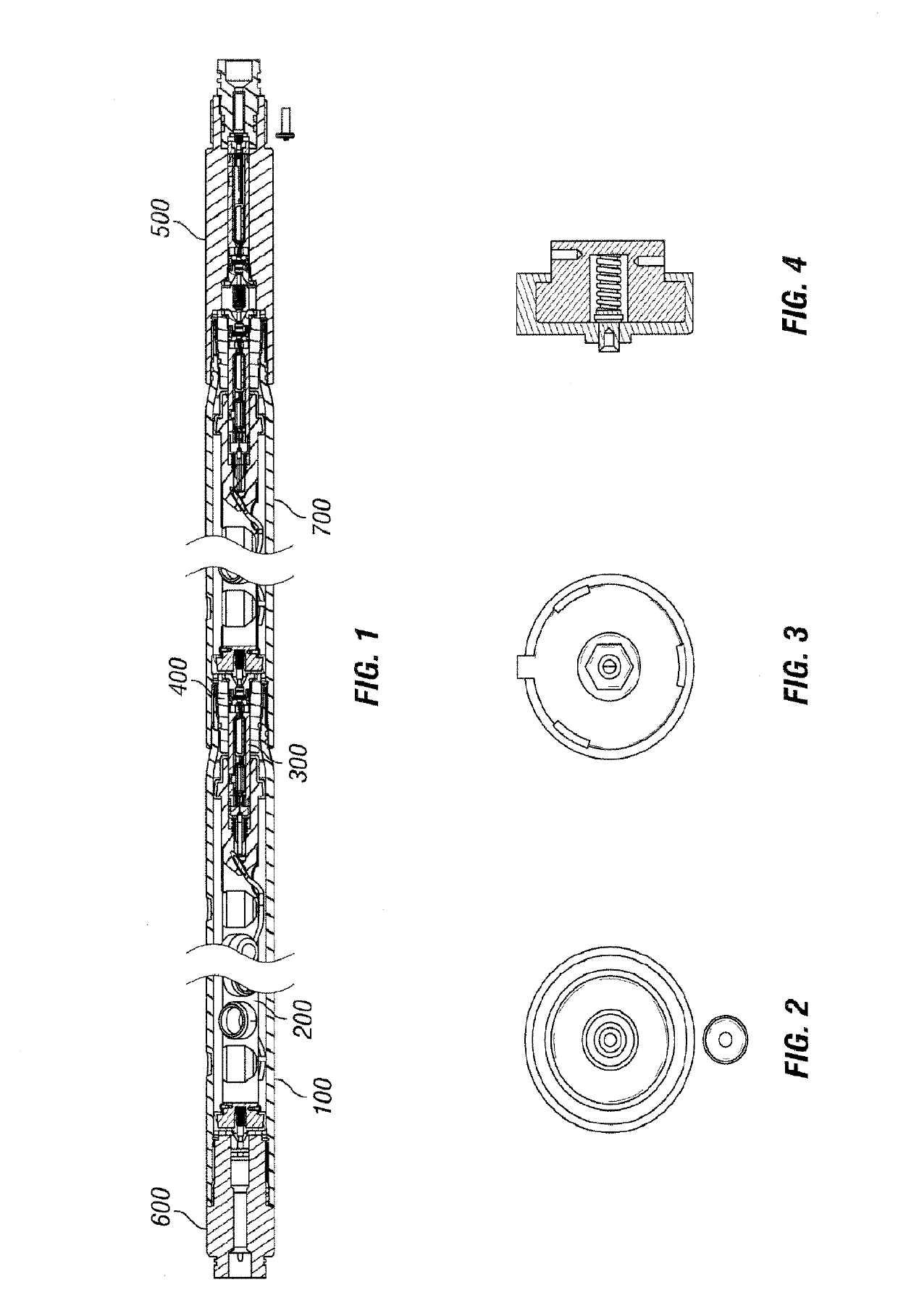
[0166]FIG. 1 illustrates one example embodiment of a perforating gun system. FIG. 1 shows a top gun adapter sub assembly 600, a first perforating gun 100, a second perforating gun 700, and a plug and shoot adapter 500.

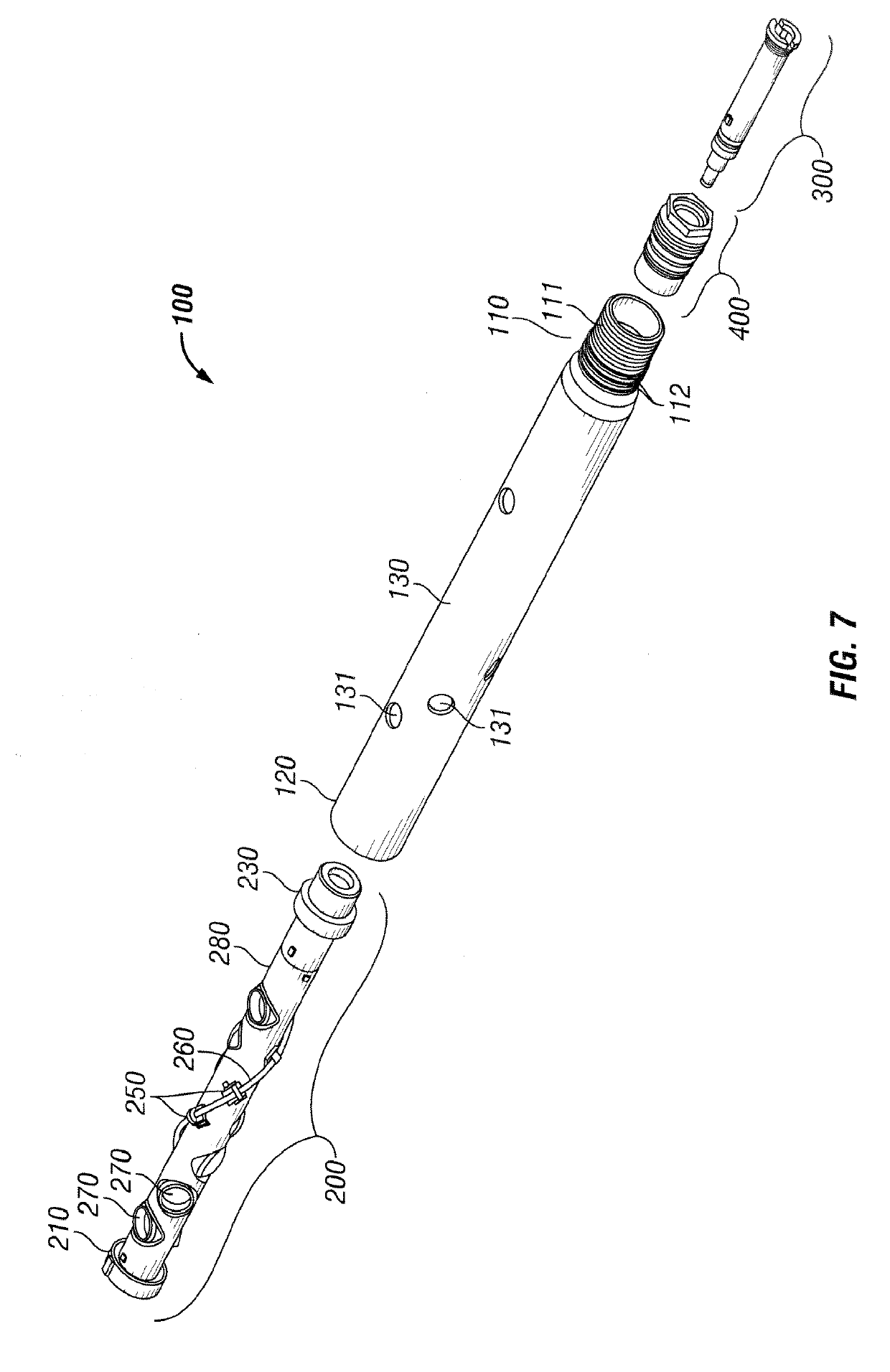
[0167]FIG. 7 shows an exploded view of example perforating gun 100. The perforating gun 100 includes a shaped charge loading tube assembly 200, a cartridge 300, and a baffle 400. Perforating gun 100 includes gun body 130. FIGS. 9, 9A, 9B, and 9C show an example embodiment of gun body 130. Gun body 130 includes a male end 110 and a female end 120. Male end 110 has an external diameter 115, a first internal diameter 113, and a second larg...


PUM


Abstract

A box by pin perforating gun system using swaged down gun bodies, a removable cartridge to hold a detonator and switch, and an insulated charge holder as an electrical feed-through.

Description

RELATED APPLICATIONS[0001]This application claims priority to U.S. Provisional Application No. 62 / 370,148, filed on Aug. 2, 2016 titled “Box by Pin Perforating Gun System”.BACKGROUND OF THE INVENTION[0002]Generally, when completing a subterranean well for the production of fluids, minerals, or gases from underground reservoirs, several types of tubulars are placed downhole as part of the drilling, exploration, and completions process. These tubulars can include casing, tubing, pipes, liners, and devices conveyed downhole by tubulars of various types. Each well is unique, so combinations of different tubulars may be lowered into a well for a multitude of purposes.[0003]A subsurface or subterranean well transits one or more formations. The formation is a body of rock or strata that contains one or more compositions. The formation is treated as a continuous body. Within the formation hydrocarbon deposits may exist. Typically a wellbore will be drilled from a surface location, placing a...

Claims


Application Information

Patent Timeline
Patent Type & Authority Applications(United States)
IPC IPC(8): E21B43/116F42D1/02F42B3/10E21B43/117E21B43/1185
CPCE21B43/116F42D1/02F42B3/10E21B43/117E21B43/1185F42C19/0838F42D1/043F42D1/04
Inventor BRADLEY, RICHARD WAYNECOLLINS, WILLIAM R.JORDAN, JOHN W.LANE, ANDYLANGFORD, DALELEVINE, CHARLESPUNDOLE, FARAIDOON
Owner HUNTING TITAN
Why Eureka
Try Eureka