Integrated opposite hook wire clamp

a technology of opposite hooks and clamps, applied in the direction of overhead installation, electric cable installation, electric cable suspension arrangements, etc., can solve the problems of wire looseness, ineffective method, wire loosening or even falling off after being used

Active Publication Date: 2020-02-06
GUANGZHOU PANYU CABLE WORKS
View PDF0 Cites 5 Cited by
  • Summary
  • Abstract
  • Description
  • Claims
  • Application Information

AI Technical Summary

Benefits of technology

[0022]The concept, the specific structure and the effects of the present disclosure will be further described with r

Problems solved by technology

This method is inefficient; besides, there is no standard set for the binding method and the binding tightness and thus the method is performed randomly, which easily leads to looseness of wire.
The wire will loosen or even fall off after being used for a long time.
The wire is usually made of metal wire such as aluminum wire, which is directly wound around the sheath of cable, which may cause damage to the sheath of cable, and further cause hazard such as cable overheating or even leakage and short circuit.
Moreover, the insulated cable in direct contact with the metal wire might cause leakage.
Currently, most of the low-voltage cables are configured by using the conventional cable fixing tool des

Method used


Image

  • Integrated opposite hook wire clamp
  • Integrated opposite hook wire clamp
  • Integrated opposite hook wire clamp

Examples


embodiment 1

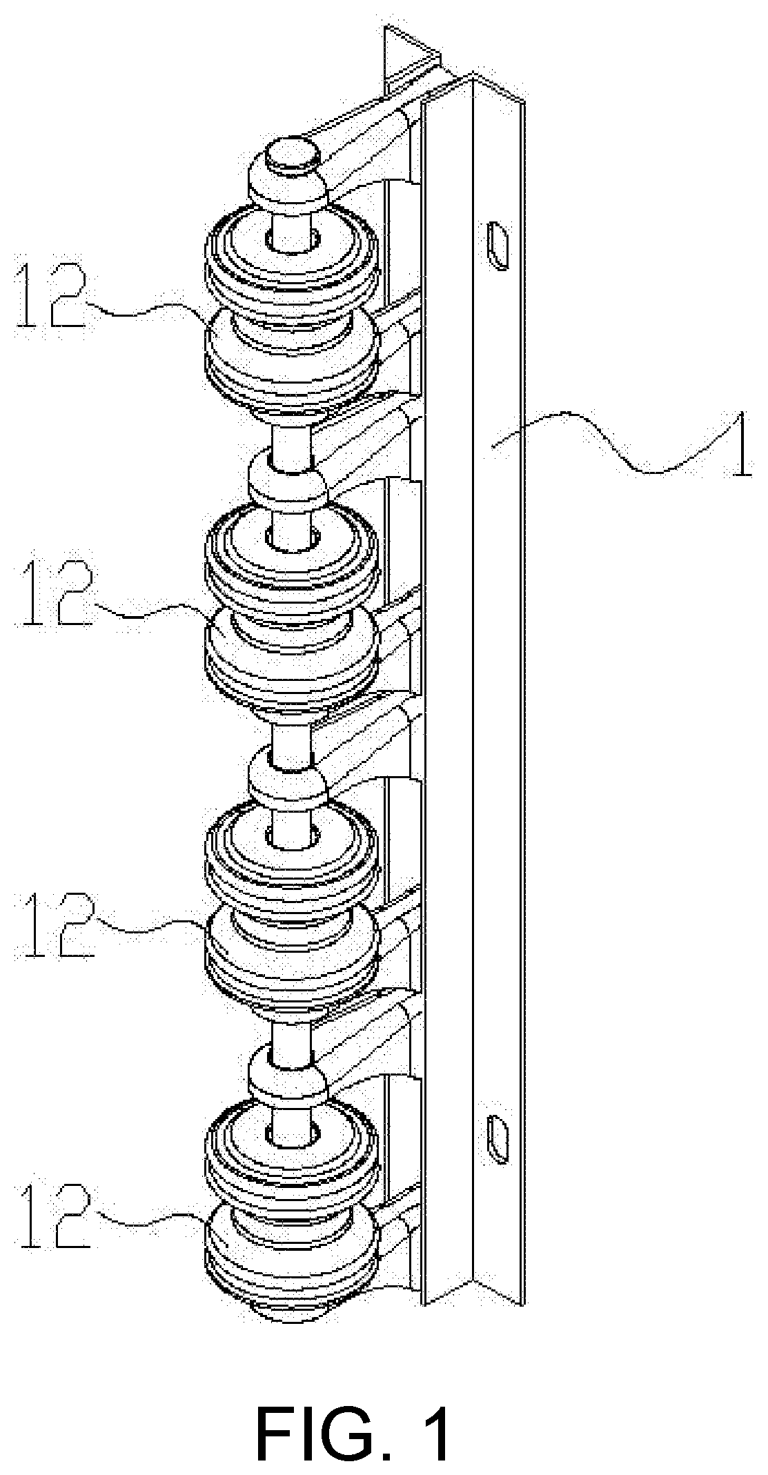
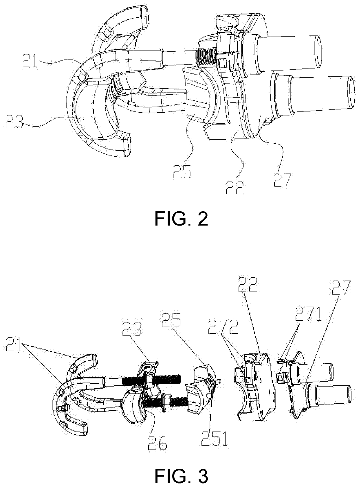
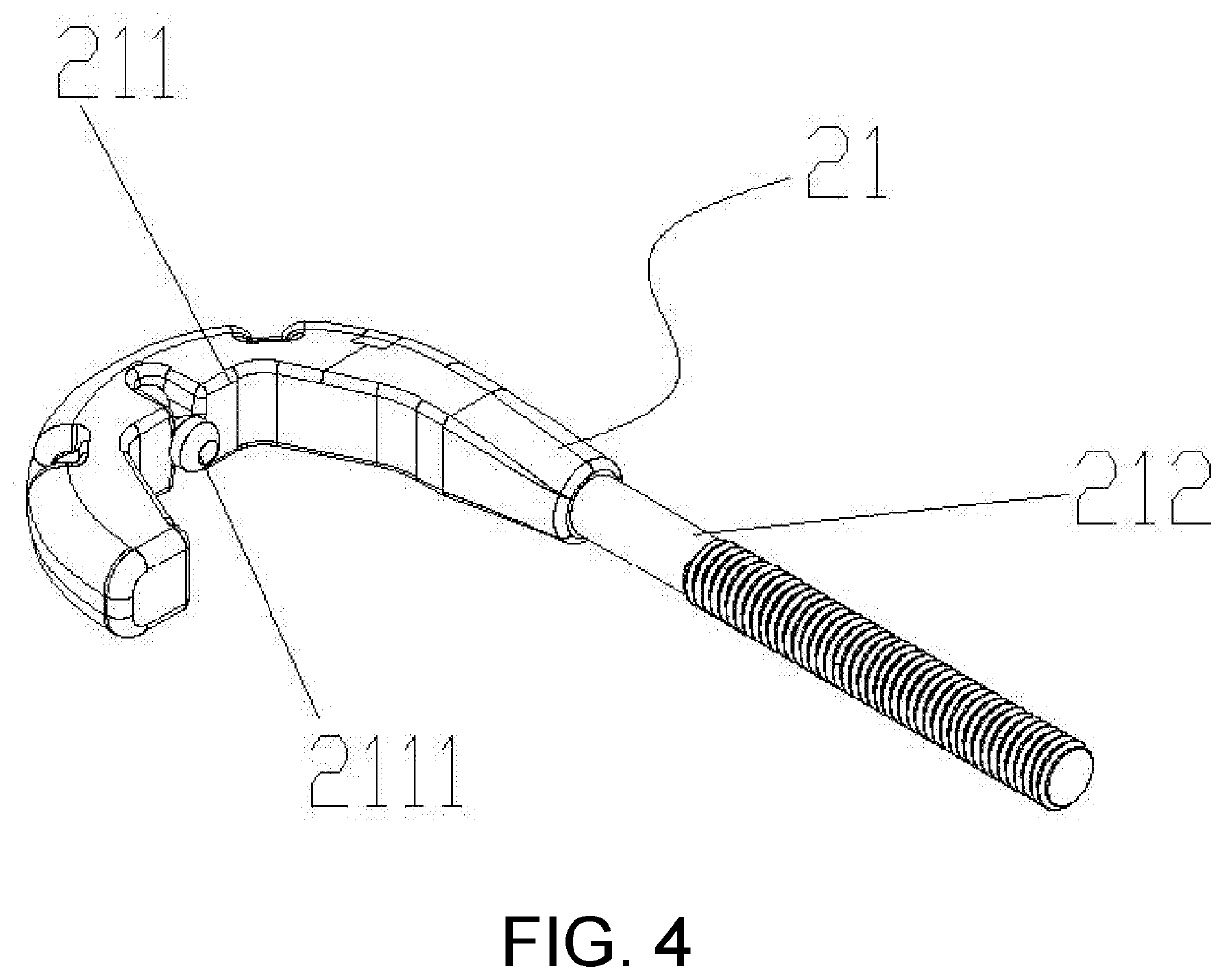
[0034]As shown in FIG. 1 to FIG. 7, an integrated opposite hook wire clamp includes a clamping plate 22, a connecting plate 23 and two J-shaped clamps 21. Side bars of the J-shaped clamps 21 are locking bars 212. The clamping plate 22 is provided with locking holes 222 corresponding to the locking bars 212, and the two locking holes 222 are diagonally disposed on the clamping plate 22. The locking bars 212 of the J-shaped clamps 21 vertically pass through the locking holes 222 on the clamping plate 22, respectively, and are movably connected to the clamping plate 22 by a locking mechanism. A back surface of the connecting plate 23 is lap-jointed to an inner side of a hook 211 of each of the two J-shaped clamps 21, and a front surface of the connecting plate 23 is opposite to a front surface of the clamping plate 22. The locking mechanism adopts a threaded connection mechanism, and each of the locking bars 212 is provided with an external thread and a corresponding nut. The locking b...

embodiment 2

[0044]On basis of the technical solution of the Embodiment 1, the locking mechanism of the integrated opposite hook wire clamp adopts an anti-reverse self-locking mechanism.

[0045]As shown in FIG. 8, the anti-reverse self-locking mechanism is configured in the manner that: each of the locking bars 212 is provided with a plurality of consecutively arranged anti-reverse ring teeth 2121 that are inclined toward a root of a corresponding one of the locking bars 212. A lateral side of each of the locking holes 222 is provided with an opening, and the opening has a movable locking block 223 disposed therein. A front end of the locking block 223 is provided with a plurality of locking teeth 2231 inclined toward an outlet of the locking hole 222 and can cooperate with the anti-reverse ring teeth 2121. The back surface of the locking block 223 abuts against the locking springs 224. When the locking bars 212 are inserted from inlets of the locking holes 222, the locking springs 224 push the lo...


PUM


Abstract

An integrated opposite hook cable clamp includes a clamping plate, a connecting plate, and at least two J-shaped clamps. Side bars of the J-shaped clamps are locking bars. Locking holes corresponding to the locking bars are provided on the clamping plate, and at least two of the locking holes are diagonally arranged on the clamping plate. The locking bars of the J-shaped clamps vertically pass through the locking holes on the clamping plate and are movably connected with the clamping plate by a locking mechanism. A back surface of the connecting plate is lap-jointed to the inner sides of hooks of each of the J-shaped clamps. A front surface of the connecting plate is opposite to a front surface of the clamping plate (22).

Description

BACKGROUNDTechnical Field[0001]The disclosure relates to the field of cable installation, in particular to an integrated opposite hook wire clamp.Description of Related Art[0002]When erecting cables, the cable is typically straightened by means of cable fixing tool. As shown in FIG. 1, the conventional cable fixing tool consists of a cable fixing bracket 1 that can be mounted on a wall or bar and an insulator 12 for supporting the cable. When the cable passes through the cable fixing tool, the cable is generally attached closely to the insulator 12, and then the cable and the insulator 12 are bundled and fixed by a wire through winding. This method is inefficient; besides, there is no standard set for the binding method and the binding tightness and thus the method is performed randomly, which easily leads to looseness of wire. The wire will loosen or even fall off after being used for a long time. The wire is usually made of metal wire such as aluminum wire, which is directly wound...

Claims


Application Information

Patent Timeline
IPC IPC(8): H02G7/05H01R11/15
CPCH01R11/15H02G7/053H02G1/04
Inventor HU, CHAOQIANGYOU, ZHANSHANSUN, JIANJIQIN, DANCHEN, XUEERLU, GUANGYEZHANG, KAITUOWANG, YANFAZHANG, SHIHUANHAO, YANSHAO, YUANPENGCHENG, XUELI
Owner GUANGZHOU PANYU CABLE WORKS
Why Eureka
Try Eureka