Supply device and method for producing a supply device

Active Publication Date: 2020-03-12
INTERROLL HLDG
View PDF11 Cites 0 Cited by
  • Summary
  • Abstract
  • Description
  • Claims
  • Application Information

AI Technical Summary

Benefits of technology

[0010]An advantage of the present invention is the increased friction, in particular static friction, between drive pulley and conveyor belt due to the friction-enhancing element configured on the drive pulley, by means of which a slipping of the drive pulley under the conveyor belt and the associated disadvantages, such as e.g. transport errors, can be reduced.
[0011]Various materials, such as e.g. metals, are suitable fora casing of the drive pulley. In particular a wear-resistant and/or rigid material with a low moment of inertia is suitable for the drive pulley. These properties are exhibited by light metals and composite materials, and in particular the casing can be made of aluminum or a steel tube covered with polyurethane (PU), e.g. with a PU having a Shore hardness of, in particular at least, about 80 D. In combination with the guide strip of the conveyor belt, a coefficient of friction μ, of about 0.1 is obtained. This allows a low-friction lateral guiding of the belt in the guide groove to be achieved. This low-friction guiding of the belt advantageously causes minimal wear and/or friction loss. Unfortunately, this low-friction combination does not provide adequate reliability for the transfer of the drive torque from the drive pulley to the running side of the conveyor belt. In a combination of the PU having a Shore hardness of, in particular at least, about 80 D with the at least one conveyor belt, which can be made of a polyvinyl chloride (PVC) on the carrying side and a polyester (PE) fabric on the running side, a friction index, in particular a coefficient of friction μ, can be only about 0.15 to about 0.2 for a static friction between conveyor belt and drive pulley. In order to increase reliability of a transfer of the drive torque, greater friction is required. This can be achieved by a higher pre-tensioning of the conveyor belt and/or a greater coefficient of friction p between conveyor belt and drive drum. However, for a higher pre-tensioning, for example higher outlay on the tensioning device, a more rigid design of the drive drum and its bearing and/or a different belt material are required, and so a greater coefficient of friction μ, in particular greater than 0.2, represents an economical and easy-to-install solution for a reliable transfer of the drive torque. An increase of the coefficient of friction μ at least in some areas, in particular in the area of the contact surface between drive pulley and running side of the conveyor belt, e.g. by friction-enhancing means, is capable of increasing reliability in the transfer of the drive torque.
[0012]The fricti

Problems solved by technology

Known supply devices may have insufficient friction between a conveyor belt and a drive pulley to drive the conveyor belt by means of the drive pulley, or in other words, the drive pulley slips under

Method used


Image

  • Supply device and method for producing a supply device
  • Supply device and method for producing a supply device
  • Supply device and method for producing a supply device

Examples


Embodiment Construction

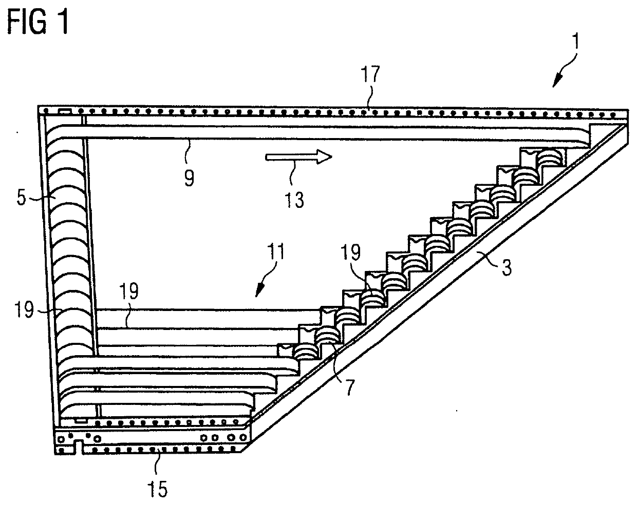
[0055]FIG. 1 shows a supply device 1 according to a first exemplary embodiment with a drive pulley 5 arranged in a frame 3 and multiple end pulleys 7, sixteen in this case, each of which is associated with a conveyor belt 9—thus with sixteen conveyor belts 9 in this exemplary embodiment. Between the drive pulley 5 and the end pulleys 7 a bed 11 is arranged. The drive pulley 5, the end pulleys 7 and the bed 11 are mounted on the frame 3.

[0056]The conveyor belts 9 are arranged approximately along a feed direction 13 shown by means of an arrow and approximately parallel adjacent to each other. The feed direction 13 points away from the drive pulley 5 towards the end pulleys 7. In this illustration, some of the conveyor belts 9 have been left out so that the construction of the supply device 1 can be seen more clearly; the bed 11 is also shown incompletely. A belt length of the respective conveyor belts 9 increases in steps from a first lateral end section 15 of the supply device 1 to a...


PUM


Abstract

A supply device for the lateral feeding of goods to be transported to a conveyor device (25), having a drive pulley (5) and at least one end pulley (7) and at least one conveyor belt (9), wherein each of the end pulleys (7) is associated with one of the conveyor belts (9), which extends around the drive pulley (5) and the associated end pulley (7) and which can be driven by means of the drive pulley (5), wherein a friction-enhancing element (41) is configured on the drive pulley (5) for enhancing friction between the respective conveyor belt (9) and the drive pulley (5).

Description

BACKGROUNDField of the Invention[0001]The invention relates to a supply device for the lateral feeding of goods to be transported to a conveyor device, and to a method for providing a supply device for the lateral feeding of goods to be transported to a conveyor device.Related Art[0002]A supply device is employed to feed goods to be transported laterally to a conveyor device. Known supply devices may have insufficient friction between a conveyor belt and a drive pulley to drive the conveyor belt by means of the drive pulley, or in other words, the drive pulley slips under the conveyor belt.[0003]To avoid this effect and the associated disadvantages, such as increased wear of the conveyor belt and / or of the drive pulley, as well as a transport error, it is an object of the present invention to provide an improved supply device that reduces transport errors.SUMMARY[0004]One aspect relates to a supply device for the lateral feeding of goods to be transported to a conveyor device. The s...

Claims


Application Information

Patent Timeline
IPC IPC(8): B65G15/64B65G23/44B65G39/16
CPCB65G15/64B65G39/16B65G23/44B65G23/04B65G15/12B65G15/46B65G15/50
Inventor DROSTE, HEINRICHDUDEK, SIEGMUND
Owner INTERROLL HLDG
Why Eureka
Try Eureka