Drainage medium for gas filter

a technology of draining medium and gas filter, which is applied in the direction of separation process, filtration separation, dispersed particle separation, etc., can solve the problems of limiting the performance of gas filters, affecting the efficiency of filtering, and not meeting quality requirements, so as to improve the drainage properties

Active Publication Date: 2020-05-21
ATLAS COPCO AIRPOWER NV
View PDF0 Cites 1 Cited by
  • Summary
  • Abstract
  • Description
  • Claims
  • Application Information

AI Technical Summary

Benefits of technology

[0015]The present invention therefore aims at providing a gas filter which offers a solution to the aforementioned problems and in particular aims to provide a gas filter with improved drainage properties.

Problems solved by technology

Air or other gases leaving a compressor often have a quality that does not meet the requirements set by the process or the application for which they are intended, unless they are adequately pretreated.
The presence of such a wet band can lead to pressure build-up in the filter and to bursting of oil bubbles on the drainage surface, which in turn can cause so-called oil transfer or “oil re-entrainment” or “oil carry over”, this is the entrainment of oil droplets through the purified air which originates from the coalescence medium and is leaving the gas filter.
This oil transfer is undesirable and can adversely affect filter efficiency.
However, the gas filters disclosed in U.S. Pat. Nos. 6,419,721 and 5,129,923 show the disadvantage that they either provide good drainage of the coalesced oil but a sub-optimal oil capture upon entering the drainage layer and thereby limit the performance of the gas filter, or they show a good absorption for the oil when entering the drainage layer, but a sub-optimal drainage, as a result of which a wet band is formed at the bottom of the drainage layer.

Method used


Image

  • Drainage medium for gas filter
  • Drainage medium for gas filter
  • Drainage medium for gas filter

Examples


example

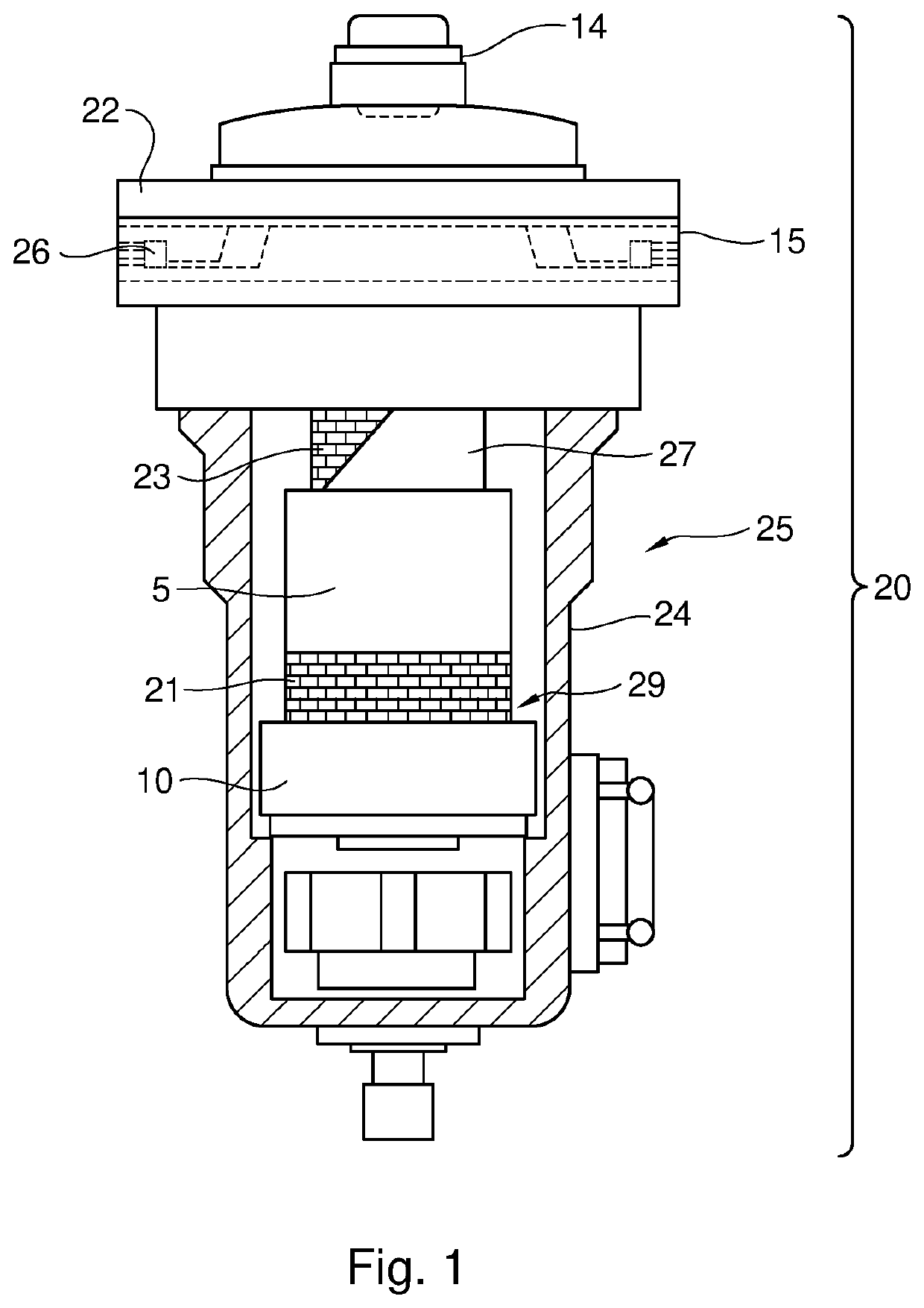
[0131]An oil-aerosol pressure filter was contacted with an air stream containing between 9 and 10 mg / m3 of oil aerosol, with an air supply velocity of 0.35 m / s and a relative pressure of 7 bar. The filter element contained a coalescence medium made of glass fiber and a three-dimensional knitted fabric as drainage medium. The pressure drop over the filter material as such amounted to 51 mbar, the total pressure drop across the oil-aerosol gas filter was 242 mbar, oil carry over was 0.004 mg / m3.

Comparative Experiment.

[0132]Example 1 was repeated, but a felt was used instead of a 3D knit. The pressure drop across the filter material as such was 49 mbar, the total pressure drop across the oil-aerosol gas filter was 290 mbar, oil carry over was 0.023 mg / m3,

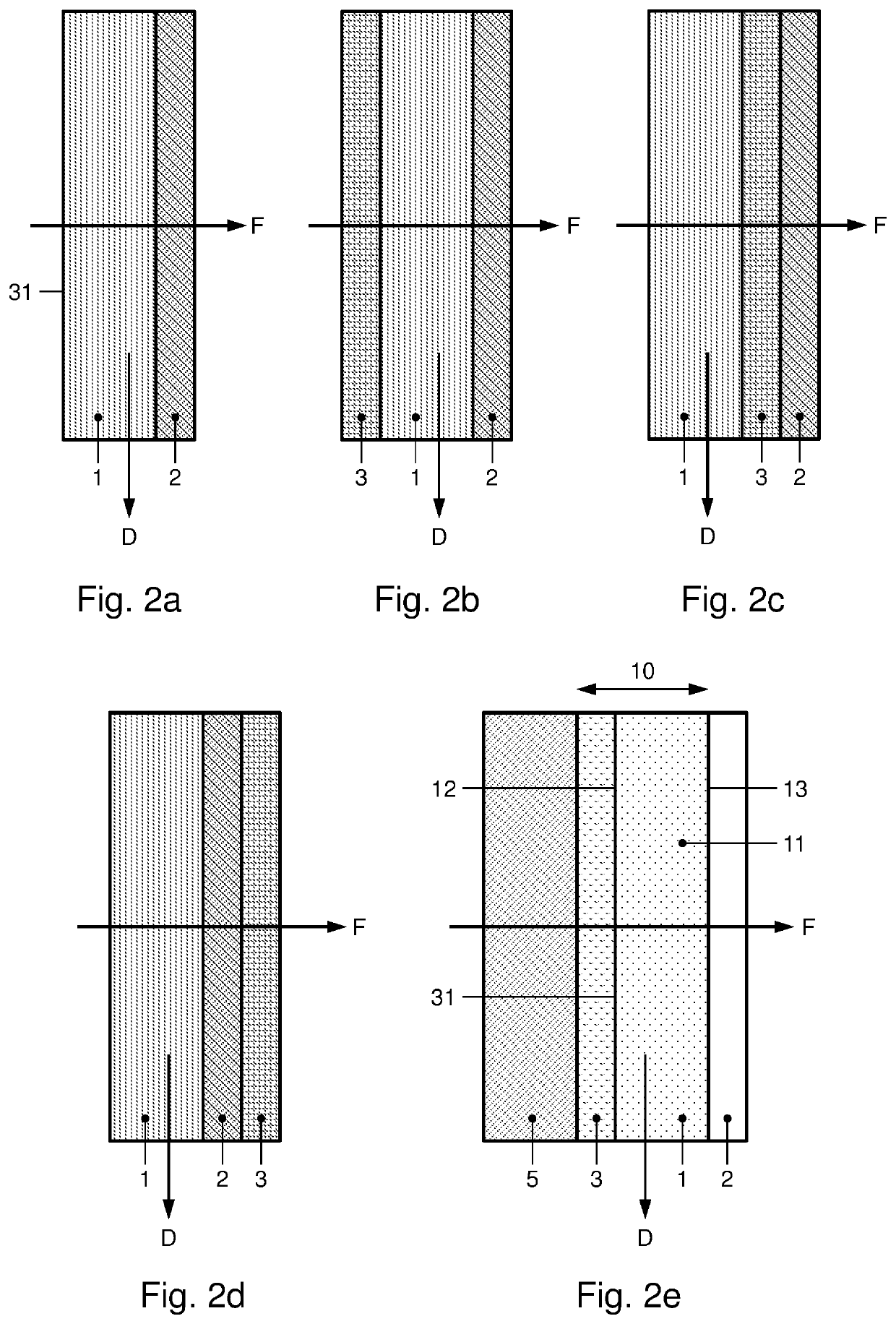
TABLE 1Suitable thicknesses for the drainage layer 1, the barrier layer 2 andthe capturing layer 3, as well as typical pore sizes for these layers.Pore size (μm)Thickness (mm)ABCABCdrainage5-2000025-10000100-25000.5-20  1-10 2-6layer 1...


PUM

PropertyMeasurementUnit
diameteraaaaaaaaaa
diameteraaaaaaaaaa
diameteraaaaaaaaaa

Abstract

A coalescence filter including an inlet for supplying the gas to a filter element present in the coalescing filter, which filter element includes a coalescence medium for coalescing at least one disperse liquid phase during a displacement of a gas through the coalescence medium in a flow direction. The filter element downstream of the coalescence medium includes a drainage medium for draining the at least one coalesced disperse phase leaving the coalescence medium. The filter element contains a barrier layer positioned downstream of the coalescence medium, where the coalescence medium and the barrier layer are held at a distance from each other by one or more spacers to provide a drainage zone in the drainage layer of a drainage medium between a surface of the coalescence medium facing the barrier layer and the barrier layer for draining the coalesced disperse phase in a drainage direction.

Description

[0001]This invention relates to a gas filter for coalescing at least one dispersed, usually liquid phase present in a gas, the gas filter comprising an inlet for supplying the gas to a filter element present in the gas filter, which filter element comprises a coalescence medium for coalescing the at least one disperse phase during a displacement of the gas through the coalescence medium in a flow direction F, wherein the filter element downstream of the coalescence medium comprises a drainage medium for draining the at least one coalesced disperse phase leaving the coalescence medium in a drainage direction D which is transverse to the flow direction F.BACKGROUND OF THE INVENTION[0002]Air or other gases leaving a compressor often have a quality that does not meet the requirements set by the process or the application for which they are intended, unless they are adequately pretreated. Examples are impurities present in compressed air or gases, including oil droplets, water droplets, ...

Claims


Application Information

Patent Timeline
Patent Type & Authority Applications(United States)
IPC IPC(8): B01D46/00
CPCB01D2239/1258B01D2239/1208B01D2258/06B01D2239/0613B01D46/0047B01D2239/0609B01D2201/184B01D46/0031B01D2239/1216B01D46/00B01D46/2418B01D46/42B01D17/045
Inventor GORIS, KENWOUTERS, JOBULTINCK, EVI MARCEL J.DE WOLF, ISABELLE DENISE M.
Owner ATLAS COPCO AIRPOWER NV
Why Eureka
Try Eureka