Terminal fitting

a terminal fitting and fitting technology, applied in the direction of coupling contact members, coupling device connections, electrical devices, etc., can solve the problems of limiting improper insertion and preventing insertion of terminal fittings

Active Publication Date: 2021-04-08
AUTONETWORKS TECH LTD +2
View PDF0 Cites 0 Cited by
  • Summary
  • Abstract
  • Description
  • Claims
  • Application Information

AI Technical Summary

Benefits of technology

[0005]The invention is directed to a terminal fitting with a rectangular tube and a stabilizer for preventing inverted insertion projecting on an outer surface of the rectangular tube. The terminal can be inserted into a cavity formed in a connector housing when the terminal fitting is facing the cavity in a proper posture. However, insertion of the terminal fitting is prohibited by the stabilizer interfering with the connector housing when the terminal fitting is facing the cavity in a posture inverted from the proper posture. An ob

Problems solved by technology

However, if the terminal fitting is in an inverted orientation by mistake, the stabilizer interferes with the connector housing to prohibit the insertion of the terminal fitting into the cavity.
Thus, the stabilizer and the cavity interfere with each other to a small extent, and there has been a concern that the terminal fitting is inserted forcibly while pushing and widening an inner wall

Method used


Image

  • Terminal fitting
  • Terminal fitting
  • Terminal fitting

Examples


first embodiment

[0022](Connector Housing 1)

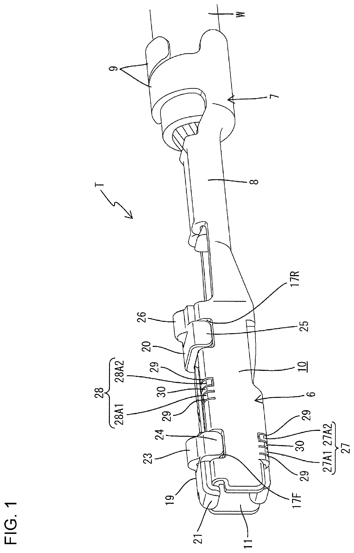
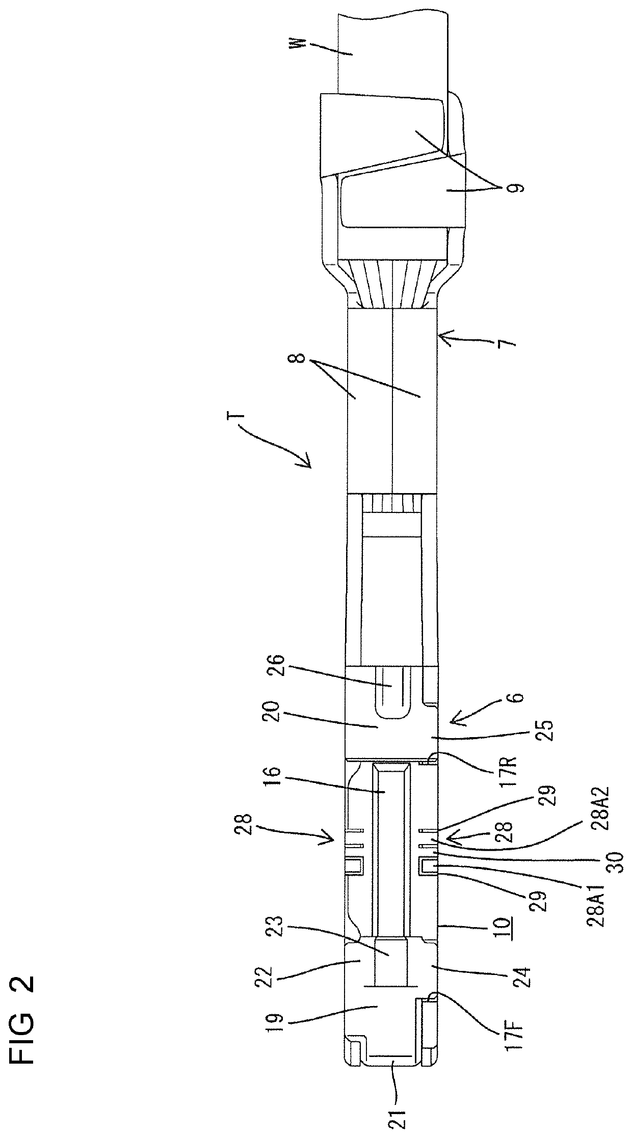
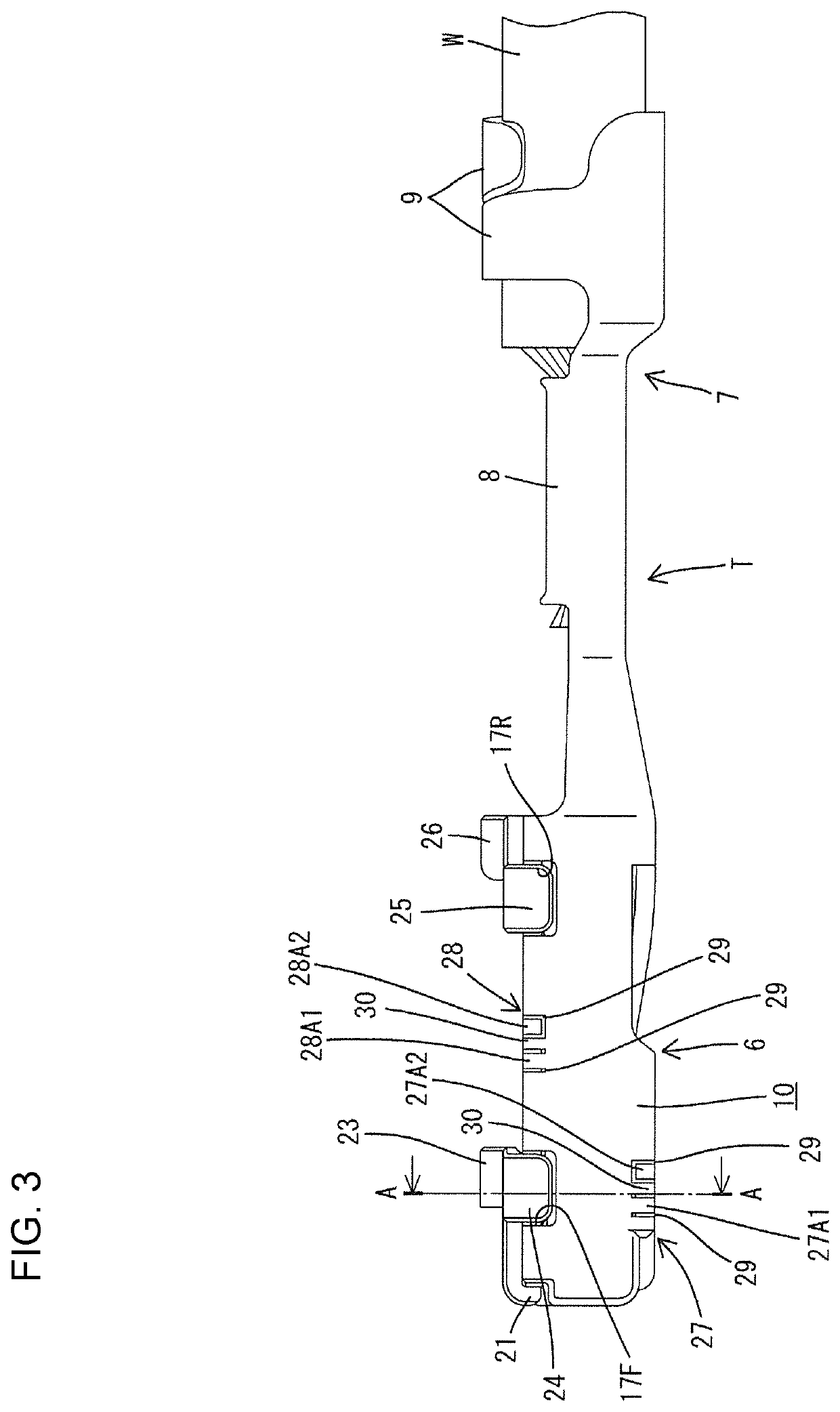
[0023]FIGS. 1 to 8 show the first embodiment of the invention. First, a connector housing 1 for accommodating terminal fittings T according to the first embodiment is described. As shown in FIG. 6, the connector housing 1 is composed of a terminal accommodating portion 2 for accommodating the terminal fittings T and a receptacle 3 surrounding the terminal accommodating portion 2. Cavities 4 for accommodating the terminal fittings T are provided in upper and lower stages in the terminal accommodating portion 2.

[0024]Each terminal fitting T is inserted into each cavity 4 from behind. As shown in FIGS. 7 and 8, each cavity 4 has a substantially rectangular cross-section long in a vertical direction and short in a width direction.

[0025]Each cavity 4 has a guide groove 5 recessed substantially over the entire length from an entrance of the cavity 4 and allows the insertion of stabilizers 23, 26 to be described later while guiding the stabilizers 23, 26 when the...

second embodiment

[0050]FIG. 9 shows the second embodiment of the invention. Although the resilient pieces 27A1, 27A2, 28A1 and 28A2 are curved in conformity with curved shapes of the corner parts of the rectangular tube 10 in the first embodiment, resilient pieces extend straight in vertical and lateral directions from a wall surface constituting a rectangular tube 10 in oblique insertion restricting portions 31, 32 in the second embodiment. As in the first embodiment, the periphery of each resilient piece 31A1, 31A2, 32A1, 32A2 is a cantilever by forming a slit 29, and is deflectable and deformable, although only to a slight extent. Further, unlike the first embodiment, the resilient pieces 31A1, 31A2, 32A1 and 32A are formed such that tip sides partially project from the periphery of the rectangular tube 10.

[0051]The other configuration is similar to the first embodiment. Hence, similar functions and effects can be achieved.

[0052]The invention is not limited to the above described and illustrated ...


PUM


Abstract

It is aimed to reliably prevent inverted insertion of a terminal fitting. Oblique insertion restricting portions (27, 28) recessed while extending in a direction intersecting an inserting direction of a terminal fitting (T) into a connector housing (1) and capable of restricting the insertion of a rectangular tube portion (10) by a material of an inner wall of a cavity (4) biting into the oblique insertion restricting portions when the terminal fitting (T) is inserted in an orientation inverted from a proper posture and in an oblique posture into the cavity (4) are provided on corner parts of the rectangular tube portion (10).

Description

BACKGROUNDField of the Invention[0001]The invention relates to a terminal fitting.Related Art[0002]Japanese Unexamined Patent Publication No. 2005-302573 discloses a female terminal fitting with a stabilizer preventing inverted insertion. The stabilizer of a female terminal fitting that is in a proper orientation will be inserted into an escaping groove in a cavity of a connector housing, thereby allowing the insertion of the terminal fitting. However, if the terminal fitting is in an inverted orientation by mistake, the stabilizer interferes with the connector housing to prohibit the insertion of the terminal fitting into the cavity.[0003]However, a worker could attempt to insert a terminal fitting in an inverted and oblique posture, i.e. where the terminal fitting is in an inverted posture diagonally facing an entrance of the cavity. In this situation, a stabilizer, which is a most projecting part from the terminal fitting, is located substantially on a diagonal of a cavity. Thus,...

Claims


Application Information

Patent Timeline
IPC IPC(8): H01R13/642H01R13/422
CPCH01R13/642H01R4/185H01R13/4226H01R13/111H01R13/4223H01R43/20H01R13/11
Inventor TAKEUCHI, SHUNYAOMORI, YASUOMIYAMURA, TETSUYA
Owner AUTONETWORKS TECH LTD
Why Eureka
Try Eureka