RFID tag

a radio frequency identification and tag technology, applied in the field of rfid tags, can solve the problems of complicated design of the entire rfid tag, and achieve the effect of improving the independence between the rfic module and the antenna

Pending Publication Date: 2022-07-28
MURATA MFG CO LTD
View PDF0 Cites 0 Cited by
  • Summary
  • Abstract
  • Description
  • Claims
  • Application Information

AI Technical Summary

Benefits of technology

[0005]Therefore, it is an object of the present invention to provide an RFID tag in which unnecessary coupling between an antenna and a coil forming an impedance matching circuit of an RFIC module is suppressed to improve independence between the RFIC module and the antenna.
[0007]According to the e International Publication No. 2016 / 084658lary embodiments of the present invention, an RFID tag is provided in which unnecessary coupling between an antenna and a coil forming an impedance matching circuit of an RFIC module is suppressed to improve independence between the RFIC module and the antenna.

Problems solved by technology

When this unnecessary coupling occurs, the RFIC module and the antenna cannot be independently designed, and the design of the entire RFID tag becomes complicated.

Method used


Image

  • RFID tag
  • RFID tag
  • RFID tag

Examples


first exemplary embodiment

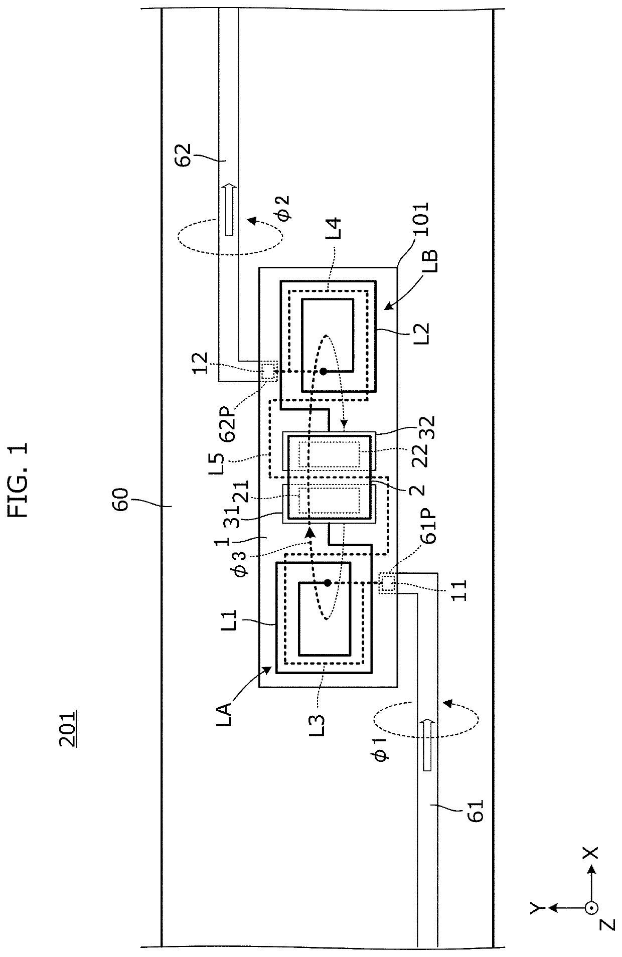
[0014]FIG. 1 is a partially enlarged plan view of an RFID tag 201 according to the first exemplary embodiment. The RFID tag 201 includes an insulator film 60, antenna conductor patterns 61 and 62 formed (or otherwise disposed) on the insulator film 60, and an RFIC module 101 mounted on the insulator film 60.

[0015]In an exemplary aspect, the antenna conductor patterns 61 and 62 form a dipole antenna. In FIG. 1, the vicinities of feeding units of the dipole antenna by the antenna conductor patterns 61 and 62 appear. A conductor pattern 61P is a feeding unit (e.g., a feeding end) of the antenna conductor pattern 61, and a conductor pattern 62P is a feeding unit (e.g., a feeding end) of the antenna conductor pattern 62.

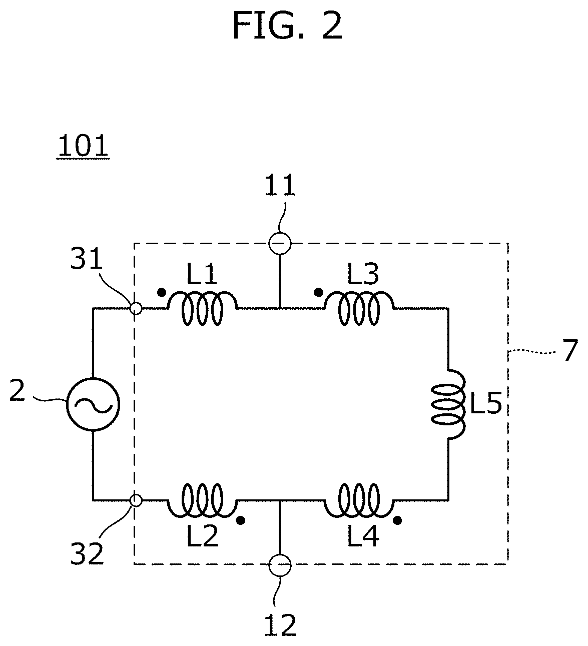
[0016]The RFIC module 101 includes a substrate 1, an RFIC 2 mounted on the substrate 1, and an impedance matching circuit formed on the substrate 1 and matching impedance between the RFIC 2 and an antenna.

[0017]The impedance matching circuit includes a first inductor L1, ...

second exemplary embodiment

[0026]In the second exemplary embodiment, in particular, an RFID tag in which the configuration of the antenna is different from that of the example shown in the first embodiment is now described.

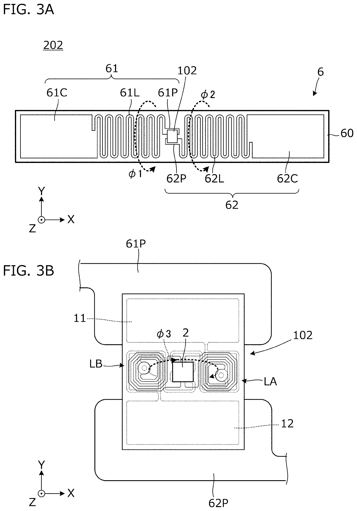
[0027]FIG. 3A is a plan view of an RFID tag 202 according to the second exemplary embodiment. FIG. 3B is an enlarged plan view of a mounting portion of an RFIC module 102 included in the RFID tag 202.

[0028]The RFID tag 202 includes an antenna 6 and an RFIC module 102 coupled to the antenna 6. Moreover, the antenna 6 includes an insulator film 60 and antenna conductor patterns 61 and 62 formed on the insulator film 60.

[0029]As shown, the antenna conductor pattern 61 includes conductor patterns 61P, 61L, and 61C, and the antenna conductor pattern 62 similarly includes conductor patterns 62P, 62L, and 62C. The antenna conductor patterns 61 and 62 form a dipole antenna in this exemplary aspect.

[0030]In addition, the RFIC module 102 is mounted on the conductor patterns 61P and 62P. The conductor...

third exemplary embodiment

[0045]In a third exemplary embodiment, in particular, an RFID tag in which a configuration of an antenna near an RFIC module is different from that in the first embodiment is shown.

[0046]FIG. 5 is a plan view of an RFID tag 203 according to the third exemplary embodiment. As shown, the RFID tag 203 includes an insulator film 60, antenna conductor patterns 61 and 62 formed on the insulator film 60, and an RFIC module 103 mounted on the insulator film 60.

[0047]The antenna conductor patterns 61 and 62 form a dipole antenna. In FIG. 5, the vicinities of feeding units of the dipole antenna by the antenna conductor patterns 61 and 62 appear. A conductor pattern 61P is a feeding unit (e.g., a feeding end) of the antenna conductor pattern 61, and a conductor pattern 62P is a feeding unit (e.g., a feeding end) of the antenna conductor pattern 62.

[0048]The RFIC module 103 includes a substrate 1, an RFIC 2 mounted on the substrate 1, and an impedance matching circuit formed on the substrate 1 ...


PUM

PropertyMeasurementUnit
intersection angleaaaaaaaaaa
impedanceaaaaaaaaaa

Abstract

An RFID tag is provided that includes an insulator film, an antenna with an antenna conductor pattern disposed on the insulator film, and an RFIC module mounted on the insulator film. The RFIC module includes an RFIC and an impedance matching circuit. The impedance matching circuit includes a first coil and a second coil. Main planes of magnetic flux loops generated in the vicinities of the first coil and the second coil by the antenna are not parallel to main planes of magnetic flux loops generated in the first coil and the second coil.

Description

CROSS REFERENCE TO RELATED APPLICATIONS[0001]The present application is a continuation of PCT / JP2020 / 031307 filed Aug. 19, 2020, which claims priority to Japanese Patent Application No. 2020-012662, filed Jan. 29, 2020, the entire contents of each of which are incorporated herein by reference.TECHNICAL FIELD[0002]The present invention relates to a radio frequency identifier (RFID) tag including a radio frequency integrated circuit (RFIC) and an antenna.BACKGROUND[0003]International Publication No. 2016 / 084658 (hereinafter “Patent Literature 1”) discloses an example of an RFID tag including an RFIC module. This RFID tag is configured by mounting an RFIC module on an antenna base material on which an antenna is formed. The RFIC module includes an RFIC and an impedance matching circuit that matches impedance between the RFIC and the antenna.[0004]In the RFIC module having the structure described in Patent Literature 1, depending on arrangement of a plurality of coils constituting the i...

Claims


Application Information

Patent Timeline
Patent Type & Authority Applications(United States)
IPC IPC(8): G06K19/077H01Q1/22H01Q1/38
CPCG06K19/07771G06K19/07786H01Q1/38H01Q1/2225G06K19/07747G06K19/07754H01Q9/285
Inventor UEKI, NORIYUKI
Owner MURATA MFG CO LTD
Why Eureka
Try Eureka