Mini DIN connector having a reduced height above a circuit board

a technology of mini din connector and circuit board, which is applied in the direction of coupling device connection, coupling protective earth/shielding arrangement, electrical equipment, etc., can solve the problem of not promoting a reduction of heigh

Inactive Publication Date: 2000-08-29
HON HAI PRECISION IND CO LTD
View PDF5 Cites 50 Cited by
  • Summary
  • Abstract
  • Description
  • Claims
  • Application Information

AI Technical Summary

Problems solved by technology

However, the connector 6 does not promote a reduced height thereof above a circuit board and a bottom thereof is not shielded against external EMI (electromagnetic interference).

Method used


Image

  • Mini DIN connector having a reduced height above a circuit board
  • Mini DIN connector having a reduced height above a circuit board
  • Mini DIN connector having a reduced height above a circuit board

Examples


Embodiment Construction

It is noted here that for facilitating understanding, like components are designated by like reference numerals throughout the various embodiments of the invention as shown in the attached drawing figures.

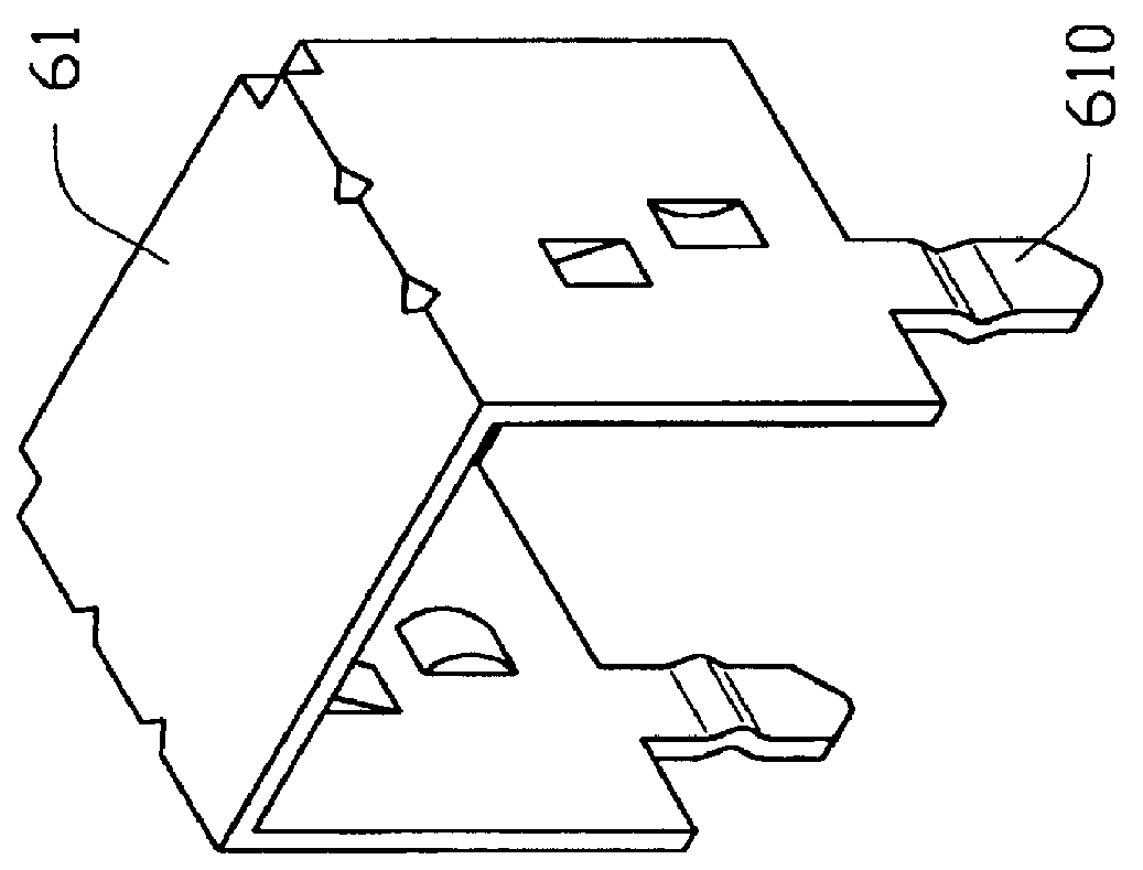
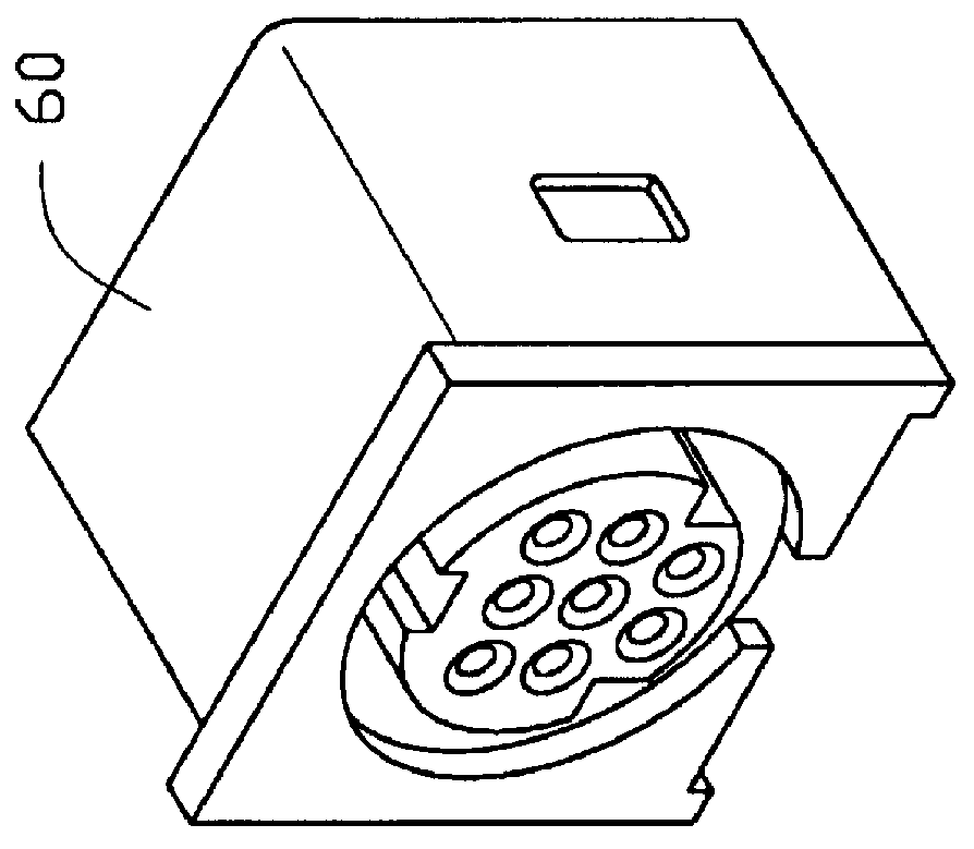
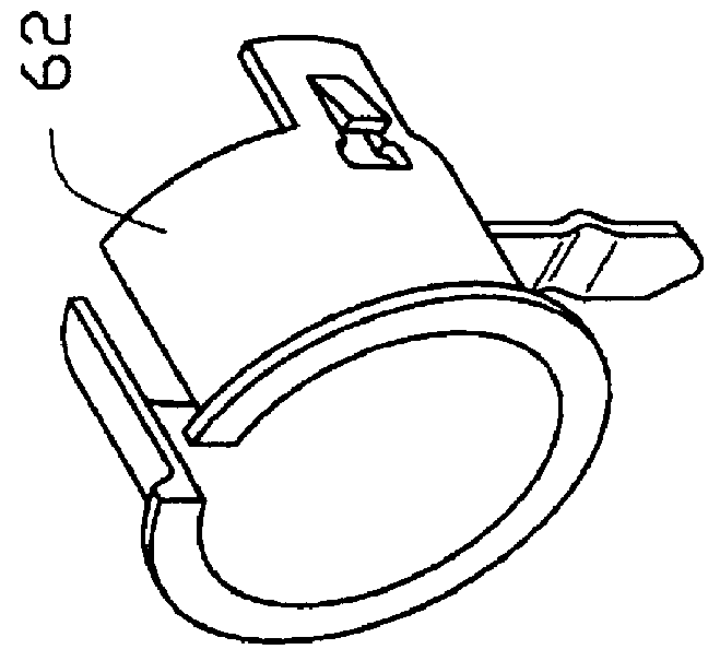
Referring to FIG. 2 and 3, a mini DIN connector comprises an insulative housing 1 with a plurality of terminal passageways 102, a plurality of terminals 2 retained in the passageways 102, a shield 3 and a bottom cover 4. The housing 1 has a mating face 10, a mounting face 11 opposite the mating face 10 and two lateral faces 12. An annular recess 101 is defined in the mating face 10 for receiving a shell member of a mating connector (not shown). A circular portion 103 extends into the recess 101 and a plurality of terminal passageways 102 are defined therethrough between the mating face 10 and the mounting face 11 for receiving the terminals 2. A T-shaped recess 110 is formed in the mounting face 11 proximate a top face 111 of the housing 1.

Further referring to FIG. 4, each lateral ...


PUM


Abstract

A mini DIN connector comprises an insulative housing, a number of terminals secured in the housing, a shield and a bottom cover. Side walls of the shield each include a cutout and an L-shaped boardlock extending from an upper edge of each cutout for securing the connector to a circuit board. The circuit board forms a cutout for receiving the connector. A support portion projects from each lateral face for engaging an edge of the cutout of the circuit board. When the boardlocks secure the connector to the circuit board, a bottom of the housing is located below the circuit board. Thus, the height of the connector above the circuit board is reduced. In addition, the bottom cover is mounted to the bottom of the housing thereby improving shielding against EMI.

Description

1. Field of The InventionThe present invention relates to a mini DIN connector, and especially to a mini DIN connector having a reduced height above a circuit board and excellent shielding capabilities.2. The Prior ArtNowadays, personal computers, especially notebook computers, are becoming increasingly compact. The entire space within a PC enclosure must be efficiently used which becomes one of the most important design considerations for connectors mounted on a mother board. Related art is disclosed in U.S. Pat. Nos. 4,913,664; 4,946,400; 5,017,158; and 5,035,651.Referring to FIG. 1, a conventional mini DIN connector 6 comprises an insulative housing 60, an external shield 61 and an internal shield 62. The external shield 61 forms a pair of boardlocks 610 adapted to secure the connector 6 to a mother board (not shown). However, the connector 6 does not promote a reduced height thereof above a circuit board and a bottom thereof is not shielded against external EMI (electromagnetic ...

Claims


Application Information

Patent Timeline
Patent Type & Authority Patents(United States)
IPC IPC(8): H01R13/658H01R12/50H01R12/70H01R13/6594
CPCH01R12/722H01R12/7064H01R13/6594
Inventor CHIOU, SONG-RONG
Owner HON HAI PRECISION IND CO LTD
Why Eureka
Try Eureka