Luminous drive system

A luminous drive and column drive technology, applied in instruments, static indicators, etc., can solve the problems of complex construction thickness and high cost of LED display, and achieve the effect of reducing construction procedures, reducing space occupied, and simple construction process.

Inactive Publication Date: 2017-08-18
SICHUAN XINGZHI ZHIHUI INTPROP OPERATION CO LTD
View PDF0 Cites 0 Cited by
  • Summary
  • Abstract
  • Description
  • Claims
  • Application Information

AI Technical Summary

Problems solved by technology

[0003] The purpose of the present invention is to provide a PX4 type light-emitting drive system to solve the problems of high cost, complicated construction and thickness of LED display screens

Method used


Image

  • Luminous drive system

Examples


Embodiment 1

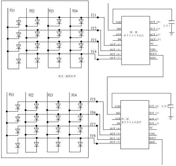
[0017] Such as figure 1 , figure 1 Only part of the area of ​​the LED matrix and two RT5958 chips are shown in the figure. In reality, the LED matrix has 60 columns and 30 rows, but only 4 columns and 8 rows are shown in the figure, but in reality there are 4 RT5958 chips, and only 2 RT5958 chips are shown in the figure, but the principle has been clearly expressed , the PX4 model is just a naming method, mainly named according to the size of the gap between the lamp beads.

[0018] Specifically, a PX4 type light-emitting drive system includes a light-emitting diode matrix, the light-emitting diode matrix is ​​composed of 60 columns and 30 rows of lamp beads arranged in a rectangular array, and the light-emitting diode matrix has 30 row input terminals and 60 column input terminals, the size of which is 256mm*128mm, also includes a row driving device, the row driving device includes 4 RT5958 chips for driving the LED matrix, and the RT5958 chips have decoding and driving fun...


PUM


Abstract

The invention discloses a PX4 type light-emitting driving system, which includes a light-emitting diode matrix, the light-emitting diode matrix is ​​composed of 60 columns and 30 rows of lamp beads arranged in a rectangular array, and the light-emitting diode matrix has 30 row input terminals and 60 column input terminals, the size of which is 256mm*128mm, and also includes a row driving device, which includes 4 RT5958 chips for driving the LED matrix, and each RT5958 chip has 1 DIN port, 8 Output ports, 1 VDD port, 1 DOUT port, the DIN port of the first-stage RT5958 chip is connected to the decoding device and receives the decoded data, the DOUT port of the previous-stage RT5958 chip is connected to the DIN port of the subsequent-stage RT5958 chip DIN port connection, 4 RT5958 chips have a total of 32 output ports, 30 output ports among the 32 output ports are connected to the 30 row input terminals of the LED matrix in one-to-one correspondence.

Description

technical field [0001] The invention relates to an LED lighting device, in particular to a PX4 model lighting driving system. Background technique [0002] The main structure of the LED display includes a matrix of light-emitting diodes, a row driver, and a column driver. The device is integrated on a PCB board, so it will increase the thickness of the LED display screen. At the same time, the traditional row driving device uses an independent decoding chip and driving chip to form a row driving device. The decoding chip receives the decoding data for decoding. Finally, the signal is transmitted to the driver chip, and the driver chip drives the lamp beads in the LED matrix according to the decoded signal. Therefore, the cost of the device is high, and the production process is complicated. Due to too many independent components, it is impossible to The decoding chip and the driver chip are fully integrated on a PCB board body, which requires an independent addition of a dr...

Claims


Application Information

Patent Timeline
Patent Type & Authority Applications(China)
IPC IPC(8): G09G3/32
CPCG09G3/32G09G2300/0404G09G2300/0408
Inventor 贺昶明
Owner SICHUAN XINGZHI ZHIHUI INTPROP OPERATION CO LTD
Why Eureka
Try Eureka