
Backlight unit and liquid crystal display device using the same

Inactive Publication Date: 2006-01-05
NEC LCD TECH CORP
View PDF25 Cites 260 Cited by
  • Summary
  • Abstract
  • Description
  • Claims
  • Application Information

AI Technical Summary

Benefits of technology

[0010] Accordingly, an exemplary feature of the present invention is to provide a backlight unit in which lights from light-emitting elements serving as light sources can be efficiently mixed and which is suitable for miniaturizing the outer shape, and to provide a liquid crystal display device using this backlight unit.
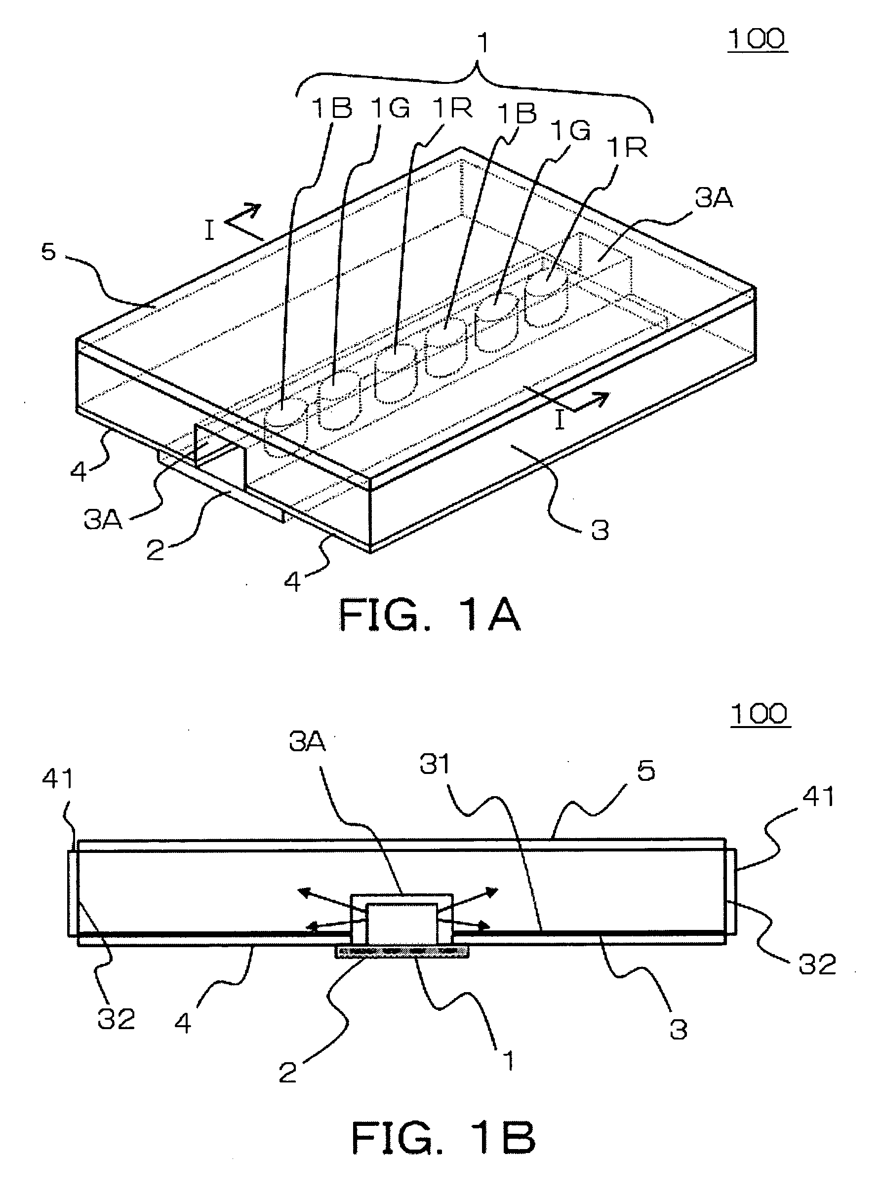
[0023] In the backlight unit of the present invention, the plurality of light-emitting elements of the side-emitting type are inserted in the recessed portion provided in the lower surface of the light guide. Further, light emitted from the light-emitting elements of the side-emitting type in the side surface directions is introduced into the light guide, and is repeatedly diffused and reflected during propagation in the light guide. Thus, color mixing of light occurs. Accordingly, lights can be efficiently mixed, and light intensity can be made uniform. Thus, backlight light can be obtained which has small color, variation over the effective lighting area and excellent color reproducibility. Additionally, since the light-emitting elements of the side-emitting type are inserted in the recessed portion provided in the lower surface of the light guide, the picture-frame area can be reduced. Further, the thickness can be reduced.
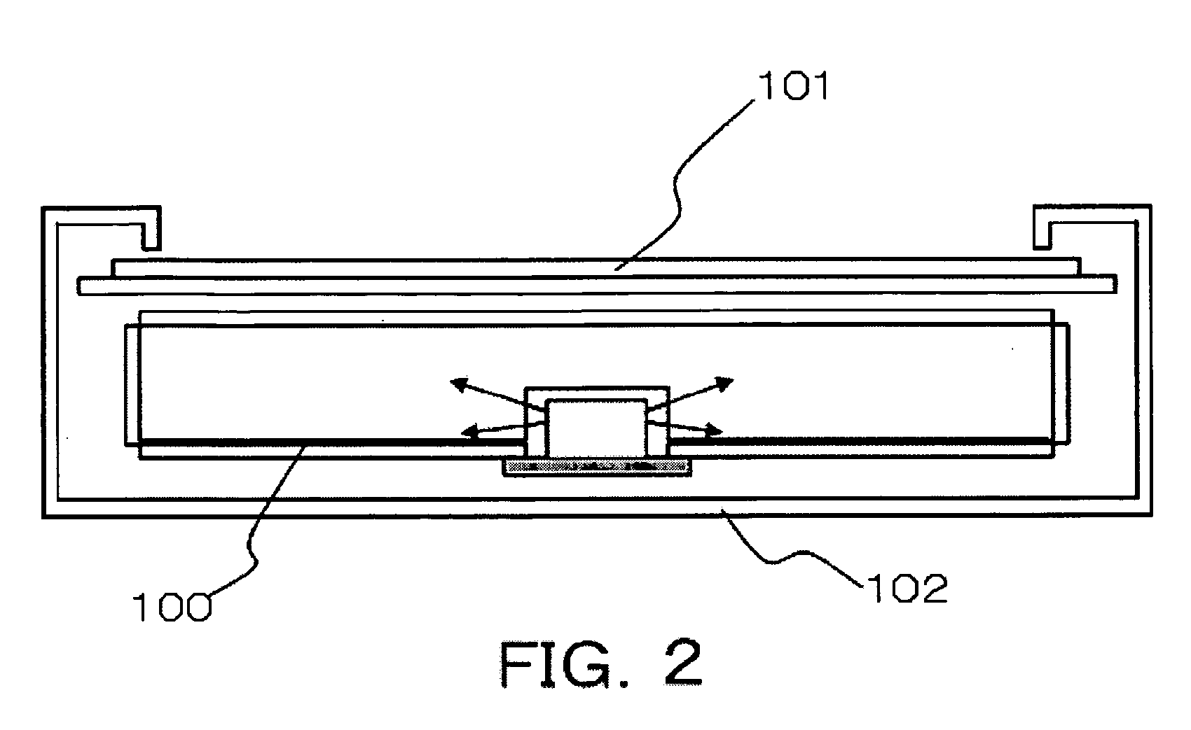
[0025] With the liquid crystal display device of the present invention, lights can be efficiently mixed, and light intensity can be made uniform. Thus, backlight light can be obtained which has small color variation over the effective lighting area and excellent color reproducibility. Since the liquid crystal panel performs display using this backlight light as illuminating light, the liquid crystal display device itself is thinned and has an outer shape of a narrow picture frame, and display which is excellent in color reproducibility can be realized.

Problems solved by technology

Accordingly, color reproducibility is not sufficient.
In particular, the color reproducibility of red is not sufficient compared to those of blue and green.
LEDs have disadvantages such as low light intensity and expensive price, compared to cold cathode fluorescent tubes.
Further, since the plurality of light guides 203 are used in a stacked manner, there is the problem that the thickness and weight of the backlight unit 200 become large.
However, this backlight unit has the problem that lights emitted from the LEDs of the light source cannot be efficiently mixed over the effective lighting area of the backlight unit.
Accordingly, there is the problem that great color variation occurs depending on the distance from the light source.

Method used


Image

  • Backlight unit and liquid crystal display device using the same
  • Backlight unit and liquid crystal display device using the same
  • Backlight unit and liquid crystal display device using the same

Examples


Embodiment Construction

[0037] Next, preferred embodiments of the present invention will be described with reference to drawings.

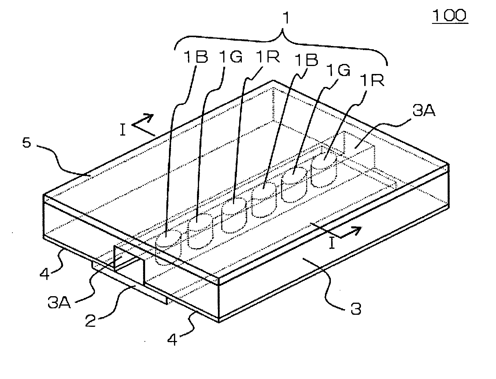
[0038] First, a first exemplary embodiment of the present invention will be described in detail with reference to drawings. A description will be given of the case where side-emitting LEDs are used as light-emitting elements of a side-emitting type. As shown in FIG. 1A, the side-emitting LEDs 1 are LEDs 1R, 1G, and 1B, each of which emits monochromatic light of Red, Green, or Blue. These are arranged in order and mounted on an LED array substrate 2. Each side-emitting LED 1 has the following light-emitting characteristics: the angle at which the emission intensity becomes maximum is within + / −20 degrees from the direction parallel to the LED array substrate 2. As such a side-emitting LED, Luxeon series of side-emitting LEDs manufactured by Lumileds Lighting can be used (see the technical document mentioned in “Description of the related art”).

[0039] A light guide 3 has upper an...


PUM


Abstract

Light emitted in side surface directions from side-emitting red, green, and blue LEDs which are arranged on an LED array substrate is introduced into a light guide from side surfaces of a groove-shaped recessed portion, and propagates in the light guide. Thus, the three colors are mixed. The light further propagates in the light guide while being reflected at both side end surfaces of the light guide by the function of a reflective sheet and the like. Thus, color mixing progresses. Further, the light is reflected upward by diffuse reflective means provided on the lower surface of the light guide, and emitted as backlight light to the outside through a diffuse sheet.

Description

BACKGROUND OF THE INVENTION [0001] 1. Field of the Invention [0002] The present invention relates to a backlight unit and a liquid crystal display device using the same. In particular, the present invention relates to a backlight unit using light-emitting diodes or the like as light sources, and a liquid crystal display device using this backlight unit. [0003] 2. Description of the Related Art [0004] In backlights for transmissive or transflective liquid crystal display devices, cold cathode fluorescent tubes have been mainly used as light sources. Since dedicated lighting circuits are necessary for cold cathode fluorescent tubes and high voltage needs to be handled, the use of light-emitting diodes instead of cold cathode fluorescent tubes has been proposed. [0005] As backlights using LEDs as light sources, there are the following known types: a type in which white light is obtained using white LEDs; and a type in which white light is obtained by arranging three types of LEDs, i.e....

Claims


Application Information

Patent Timeline
IPC IPC(8): F21V7/04
CPCG02B6/0021G02B6/0055G02B6/0068G02F1/133611G02F1/133603G02F1/133609G02B6/0073G02F1/1335
Inventor BABA, MASATAKE
Owner NEC LCD TECH CORP
Learn More