Multiphase mixing device with baffles

Active Publication Date: 2006-05-16
EXXON RES & ENG CO
View PDF20 Cites 47 Cited by
  • Summary
  • Abstract
  • Description
  • Claims
  • Application Information

AI Technical Summary

Benefits of technology

[0012]Another aspect of the present invention provides improvement in connection with gas phase mixing by providing an incremental increase in the volume available for gas mixing by

Problems solved by technology

First, the quench zone fails to erase lateral temperature differences at the outlet of the preceding bed or, in the worst cases, amplifies them.
The second sign of poor performance is that inlet temperature differences following the quench zone increase as the rate of quench gas is raised.
This indicates inadequate mixing of cooler gas with the hot process fluids.
Poor quench zone performance limits reactor operation in various ways.
When interbed mixing is unable to erase temperature differences, these persist or grow as the process fluids move down the reactor.
Hot spots in any bed lead to rapid deactivation of the catalyst in that region which shortens the total reactor cycle length.
Product selectivities are typically poorer at high temperatures; hot regions can cause color, viscosity and other qualities to be off-specification.
), the exothermic reactions may become self-accelerating leading to a runaway which can damag

Method used


Image

  • Multiphase mixing device with baffles
  • Multiphase mixing device with baffles
  • Multiphase mixing device with baffles

Examples


Embodiment Construction

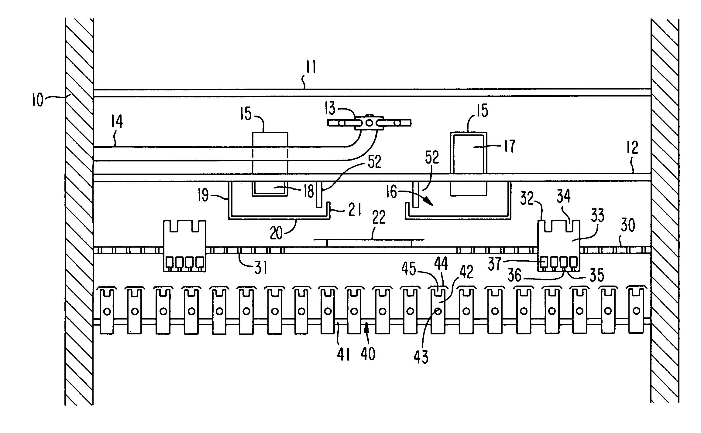
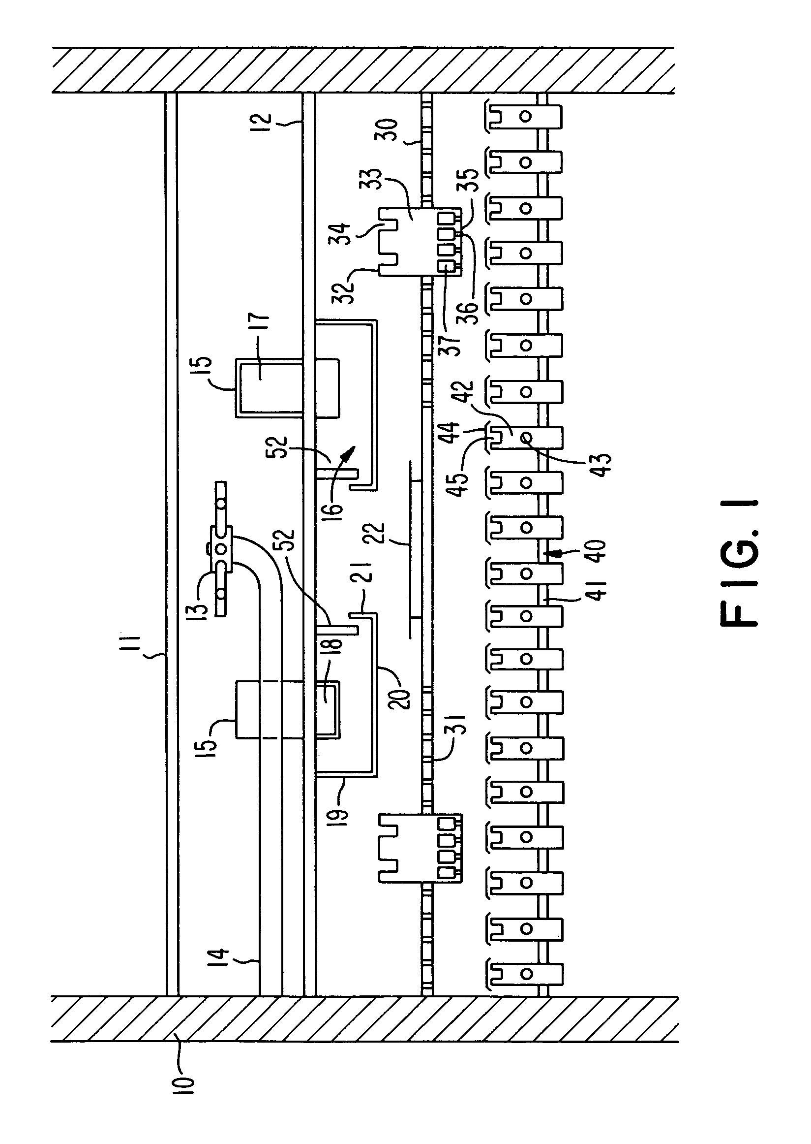
[0017]FIG. 1 shows, in simplified form, a section through the portion of a multiple bed, downflow reactor in the region between the beds. The general configuration of the downflow reactor is conventional, as are details such as the supports for the grids and distributor plates which are not shown for purposes of clarity. The walls 10 of the reactor and the catalyst support grid 11 support an upper bed of catalyst or other particulate solid over which the liquid is to flow together with any vapor included as the reactant or as a product of the reaction. For clarity, the catalyst is not shown. The support grid may be of conventional type and provides support for the catalyst either directly or by means of support balls which permit the liquid and vapor to flow downwardly out of the upper bed of catalyst and through the grid to the distributor system beneath. A collection tray 12 is disposed beneath the catalyst support grid 11 to collect the liquid leaving the upper catalyst bed. The ...


PUM

PropertyMeasurementUnit
Radiusaaaaaaaaaa
Perimeteraaaaaaaaaa

Abstract

The present invention provides a novel means to provide more effective mixing of quench gas and process fluids in a height constrained interbed space of a catalytic reactor without increasing pressure drop. In particular, the device improves the effectiveness of an existing mixing volume in mixing the gas phase of two-phase systems. According to the present invention, the quench zone hardware contained within the reactor includes a substantially vertical continuous perimeter solid baffle attached to the underside of the collection tray.

Description

FIELD OF THE INVENTION[0001]The present invention relates generally to systems for mixing process gases and liquids and more specifically to interbed quench and mixing systems involving cocurrent downflow reactors using fixed hardware.BACKGROUND OF THE INVENTION[0002]In fixed-bed fuels and lube hydroprocessing units, gas and liquid flow downward through multiple beds of solid catalyst. Heat is released from the catalytic reactions causing temperature to increase with distance down the bed. Cool hydrogen-rich gas is introduced between the beds to quench the temperature rise and replenish the hydrogen consumed by the reactions. Three requirements of an effective quench zone are transverse gas mixing, transverse liquid mixing, and quench gas mixing.[0003]The introduction and mixing of quench into the process gas and liquid must be carried out in the interbed space which spans the full vessel diameter, but is often shorter than one vessel radius. Support beams, piping and other obstruct...

Claims


Application Information

Patent Timeline
IPC IPC(8): B01J10/00B01J8/02B01F3/04B01J8/04C10G45/00C10G49/00
CPCB01J8/0492C10G49/002B01J2208/00849
Inventor MCDOUGALD, NEIL K.BOYD, SHERRI L.MULDOWNEY, GREGORY P.
Owner EXXON RES & ENG CO
Why Eureka
Try Eureka