Mixing device for a down-flow reactor

a hydroprocessing reactor and mixing device technology, applied in the direction of solvent extraction, physical/chemical process catalysts, separation processes, etc., can solve the problems of limiting the operation of the reactor in various ways, and reducing the efficiency of the hydroprocessing reactor. , to achieve the effect of improving the effectiveness improving the efficiency of the existing mixing volume, and small siz

Active Publication Date: 2011-09-13
CHEVROU USA INC
View PDF17 Cites 46 Cited by
  • Summary
  • Abstract
  • Description
  • Claims
  • Application Information

AI Technical Summary

Benefits of technology

[0005]The invention provides a novel means to provide more effective mixing of fluids in the space between catalyst beds in a multi-bed reactor. In particular, the invention is direct to a mixing device that improves the effectiveness of an existing mixing volume in mixing the gas phase and liquid phase of two-phase systems. The device is well suited for retrofit applications due to its relatively small size and can also be scaled for new reactor designs to achieve efficient fluid mixing in the interbed space of a multi-bed reactor.
[0009]In an embodiment, fluids overflow the flow stabilizer and collect in the interstitial space between the flow stabilizer and the riser in a second mixing zone. The riser and flow stabilizer are designed to increase swirling and turbulence of the fluids allowing more effective mixing and temperature equilibration. In an embodiment, one or more perforated plates can be attached to the riser and / or flow stabilizer. If perforated plates are present, the fluids flow over and / or through the perforated plates, increasing droplet formation and improving mixing. The fluids enter a plurality of slots of a bubble cap 85 and overflow the top of the riser before entering the annular outlet region. The bubble cap 85 is attached to the top wall 49 of the mixing device 40 and descends parallel to the divider 45 and riser 75. The bubble cap 85 is approximately mid-way between the exterior wall of the riser 75 and the interior wall of the flow stabilizer 60. The bubble cap 85 is disposed over and about the riser 75 such that the top of the cap is above the top of the riser so as to provide a passageway for the fluids to enter the third mixing zone. The bubble cap 85 is generally cylindrical and has a diameter larger than the riser 75 but smaller than the diameter of the flow stabilizer 60 as measured from the top of the flow stabilizer to the center axis of the mixing device. The third mixing zone is defined by the annular passageway between the outer surface of the riser and the inner surface of the bubble cap. The slots 86 of the bubble cap 85 are substantially symmetrically disposed about the circumference of the bubble cap's open end and begin at the lower extremity and ascend substantially vertically up a portion of the bubble cap. This configuration allows fluids to pass from the second mixing zone to the third mixing zone prior to egress through the annular outlet.
[0010]The inner wall of the cylindrical walled riser forms the annular outlet 90. Optionally attached to the inner wall of the riser is a helicoidal perforated plate 75 which acts as a baffle to increase droplet formation and improve fluid mixing. The helicoidal perforated plate 75 does not extend the full diameter of the annular outlet 90. The helicoidal plate forms a semi-spiral baffle that is optionally fixed to the inner wall of the riser in the outlet region of the mixing device. Fluids egress the mixing device through the outlet and discharge on to the interbed re-distributor tray 31, FIG. 1, before contact the subsequent catalyst bed. Quench gas or fluid may be injected at multiple points into the collection plate or into the mixing device as desired.

Problems solved by technology

Poor interbed fluid mixing can limit reactor operation in various ways.
When interbed mixing is unable to erase temperature differences, these persist or grow as the process fluids move down the reactor.
Hot spots in any bed can lead to rapid deactivation of the catalyst in that region which shortens the total reactor cycle length.
Product selectivities are typically poorer at high temperatures.
), the exothermic reactions may become self-accelerating leading to a runaway which can damage the catalyst, the vessel, or downstream equipment.
Due to these hazards, refiners operating with poor internal hardware must sacrifice yield and / or throughput to avoid the deleterious effects of poor interbed fluid mixing.
The interbed space in many reactors is limited due to the presence of support beams, piping, and other obstructions which occupy the interbed region.

Method used


Image

  • Mixing device for a down-flow reactor
  • Mixing device for a down-flow reactor
  • Mixing device for a down-flow reactor

Examples


Embodiment Construction

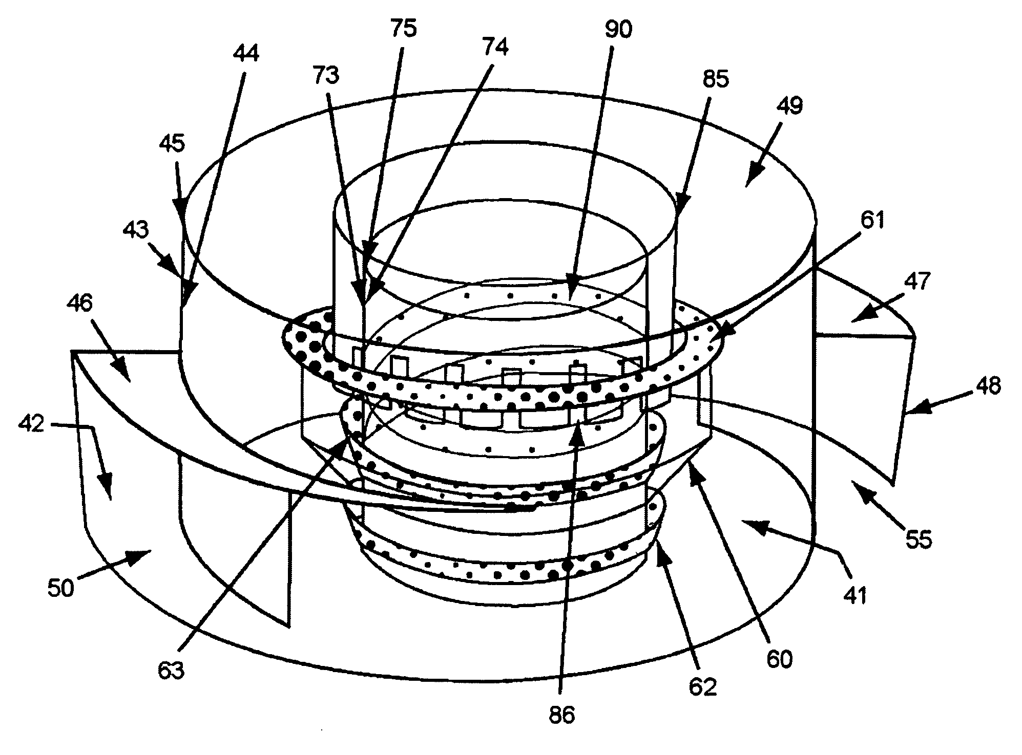
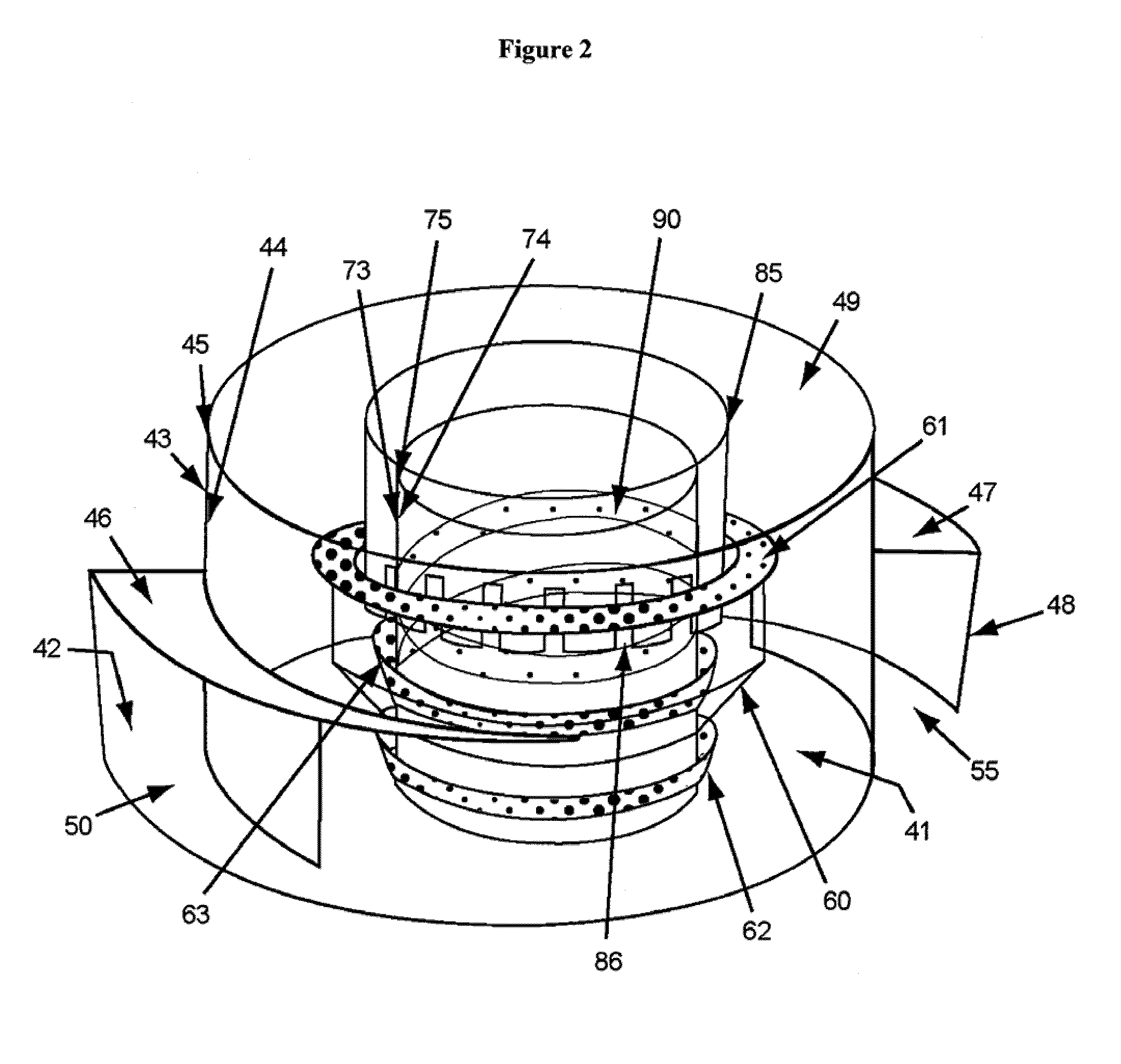
[0016]In an embodiment, the mixing device of the invention is centrally disposed on top of the collection plate and between the catalyst support beams. The mixing device of the invention has at least one inlet for receiving fluids from the trough. In an embodiment, the mixing device has two inlets to receive fluids from the collection plate. The use of two inlets oriented at 180 degrees from each other with their openings situated so as to reinforce the circular, swirling motion of the incoming fluids improves the turbulence effect of the mixing device design.

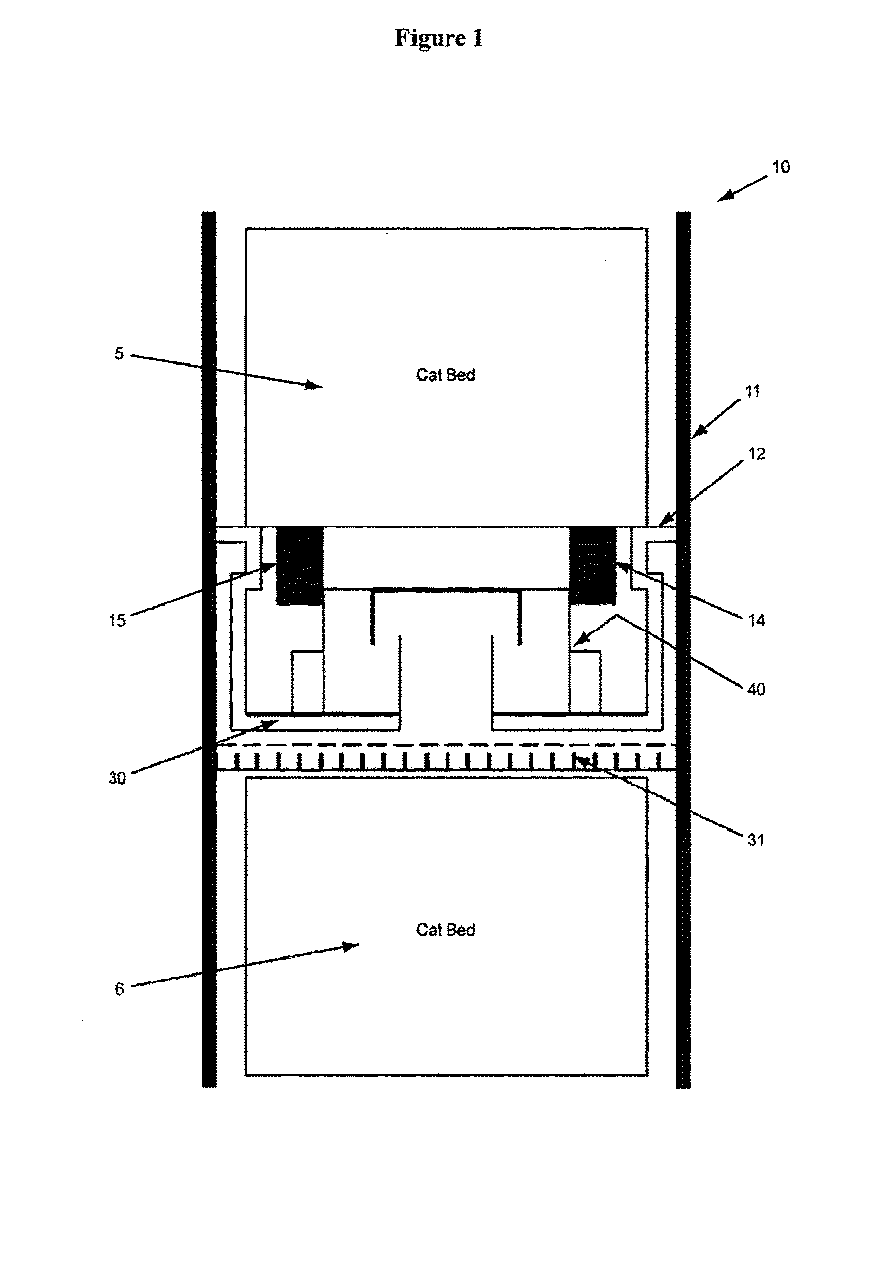
[0017]As shown in FIG. 1, a multi-bed, down-flow reactor 10 has a cylindrical sidewall 11. The section shown in FIG. 1 is a cross section of a multi-bed catalytic reactor. Each catalyst bed, 5 and 6, contain packed particulate catalytic material. Each catalyst bed is supported on a grid screen assembly 12 comprised of a support grid, space cloth and wire screen, all of which are well known in the art. The grid screen assembly i...


PUM

PropertyMeasurementUnit
temperatureaaaaaaaaaa
angleaaaaaaaaaa
heightaaaaaaaaaa

Abstract

The present invention provides a novel means to provide more effective mixing of gas and fluids in a height constrained interbed space of a catalytic reactor without increasing pressure drop. In particular, the device improves the effectiveness of an existing mixing volume in mixing the gas phase and liquid phase of two-phase systems. According to the present invention, the mixing device helps create a highly arcuate flow to incoming effluents and a high degree of mixing within a constrained interbed space of a catalytic reactor.

Description

FIELD OF THE INVENTION[0001]This invention relates to a mixing device for multi-bed hydroprocessing reactors. Specifically, the mixing device is for use in down-flow catalytic reactors which include vertically superimposed packed beds of particulate catalytic material wherein a liquid or liquid and gas mixture is processed as it flows down through the packed beds. This type of reactor is used in the petroleum and chemical processing industries for carrying out various catalytic reactions, such as hydroprocessing reactions including hydrotreating, hydrofinishing, hydrocracking, and dewaxing.BACKGROUND OF THE INVENTION[0002]In fixed-bed fuels and lube hydroprocessing units, gas and liquid flow downward through multiple beds of solid catalyst. Heat is released from the catalytic reactions causing temperature to increase with distance down the bed. Cool hydrogen-rich gas can be introduced between the beds to quench the temperature rise and replenish the hydrogen consumed by the reaction...

Claims


Application Information

Patent Timeline
Patent Type & Authority Patents(United States)
IPC IPC(8): B01J8/10B01J19/00B01J35/02
CPCB01F5/0057B01J8/0085B01J8/0453C10G65/02B01J8/0492B01J2208/00938B01J2208/00929B01J2208/00849B01F25/10B01J8/04B01F23/20B01F35/71
Inventor KEMOUN, ABDENOURSONG, STEVEN X.
Owner CHEVROU USA INC
Why Eureka
Try Eureka